Elastic pre-tightening terminating stepless multidirectional large floating interconnection structure

An elastic pre-tightening and interconnection structure technology, which is applied in the direction of connection, contact parts, and parts of the connection device, can solve the problem of inability to achieve a wide range of axial floating, the inability to meet the floating amount of interconnection structures, metal panels and connections In order to achieve stable and reliable elastic modulus, wide application value and simple and reliable part structure

Pending Publication Date: 2022-03-01
CHINA AVIATION OPTICAL-ELECTRICAL TECH CO LTD
View PDF13 Cites 0 Cited by
  • Summary
  • Abstract
  • Description
  • Claims
  • Application Information

AI Technical Summary

Problems solved by technology

After the backplane connector is welded on the filter backplane, when it cooperates with the metal panel as a whole, there will be a problem: the relative position of the metal panel and the connector must be within ±0.2mm, especially on the panel. is more serious when the number of connectors is relatively large
[0005] 2) The current elastic needle structure cannot achieve a wide range of axial floating. The current elastic needle technology can only achieve ±0.5mm axial floating. Higher axial floating requirements will increase the reliability of the elastic needle
[0006] 3) To maintain the reliability and axial floating ability of the elastic pin, the elastic pin contact must be designed to be relatively long and have a large diameter to ensure function and reliability. This will undoubtedly increase the production cost of the elastic pin and cannot be used in the connector. get common in
[0007] For the existing ±1.5mm radial float and axial float of more than ±3mm, there is no interconnection structure in the market that can meet such a large float

Method used


Image

  • Elastic pre-tightening terminating stepless multidirectional large floating interconnection structure
  • Elastic pre-tightening terminating stepless multidirectional large floating interconnection structure
  • Elastic pre-tightening terminating stepless multidirectional large floating interconnection structure

Examples


Embodiment Construction

[0075] In order to further explain the technical means and effects of the present invention to achieve the intended purpose of the invention, the following, in conjunction with the accompanying drawings and preferred embodiments, will discuss the elastic preload terminal stepless multi-directional large floating interconnection structure proposed according to the present invention. Specific embodiments, structures, features and effects thereof are described in detail below.

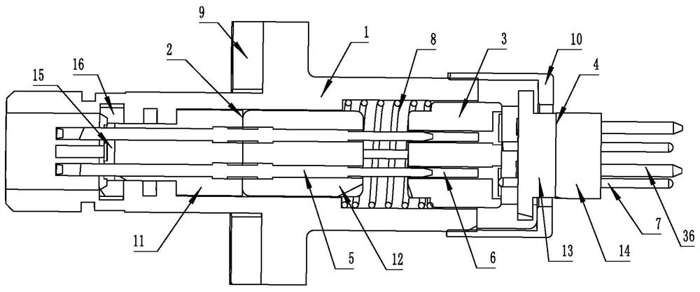
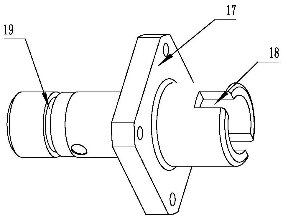
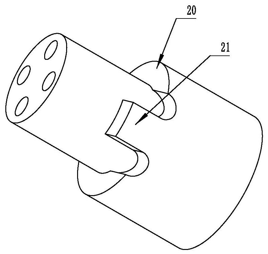
[0076] see Figure 1-12 , which is a structural schematic diagram of each part of the elastic pre-tightening terminal stepless multi-directional large floating interconnection structure of the present invention, the structure includes a housing 1, and the front insulator is sequentially installed in the housing 1 along its axial direction from front to back 2. The floating insulator 3 and the bottom insulator 4, wherein the front insulator 2 is fixedly assembled in the casing 1, the floating insulator 3 a...


PUM


Abstract

The invention relates to an elastic pre-tightening terminating stepless multidirectional large floating interconnection structure which comprises a shell, a front insulator, a floating insulator and a bottom insulator are arranged in the shell along a shaft, the front insulator is fixedly assembled in the shell, and the floating insulator and the bottom insulator are both assembled in the shell in a sliding mode. A gap meeting the radial floating requirement is formed between the bottom insulator and the shell; an axial pre-tightening spring used for providing force away from the front insulator for the floating insulator and the bottom insulator is further arranged in the shell, and a stop piece used for preventing the bottom insulator from disengaging is further arranged at the tail of the shell. In the sliding stroke of the floating insulator, the front end of a disc contact in the floating insulator and the rear end of a front contact in the front insulator are always kept in insertion fit through the cooperation of a long pin and a long hole, and a pin at the front end of a printed board contact in the bottom insulator is always in contact with the disc end face at the rear end of the disc contact. And when the bottom insulator radially floats, the contact pin slides on the end surface of the disc.

Description

technical field [0001] The invention belongs to the technical field of connectors, and in particular relates to a stepless multi-directional large floating interconnection structure for elastic pre-tightening terminations. Background technique [0002] At present, there are many types of electrical connectors, and their application range is very wide. In particular, the fire control chassis and information processing chassis that are widely used in the new generation of tanks or radar platforms, the filter panel structure of the box has been more and more reflected and applied. The structural design of the filter panel specifically includes several parts, the filter backplane, the backplane connector (including circular and rectangular connectors) and the metal panel. After the backplane connector is welded on the filter backplane, when it cooperates with the metal panel as a whole, there will be a problem: the relative position of the metal panel and the connector must be ...

Claims


Application Information

Patent Timeline
Patent Type & Authority Applications(China)
IPC IPC(8): H01R13/631H01R13/24
CPCH01R13/6315H01R13/24
Inventor 杨尚矗杨成博张永星胡晓松
Owner CHINA AVIATION OPTICAL-ELECTRICAL TECH CO LTD
Why Eureka
Try Eureka