
Rapid cooling forming mold

A fast, mold-based technology, applied in the field of molds, can solve the problems of low production cost, inability to cool and form workpieces, and high cost, and achieve good and fast water cooling effects, simple molds, and trouble-saving effects

Inactive Publication Date: 2019-09-27
GUIZHOU UNIV
View PDF2 Cites 1 Cited by
  • Summary
  • Abstract
  • Description
  • Claims
  • Application Information

AI Technical Summary

Problems solved by technology

[0002] The mold is a rapid prototyping engraving tool, which consists of an upper mold base and a lower mold base. The mold is a tool used to make shaped objects. This tool is composed of various parts. Different molds are composed of different parts. It mainly realizes the processing of the shape of the object through the change of the physical state of the formed material. It has a good engraving effect and low production cost, and is widely used in various fields; the existing molds have certain disadvantages when used. The internal workpiece cannot be cooled and formed quickly, and the internal workpiece cannot be ejected more conveniently. Generally, it is manually disassembled, or it needs to be ejected by other power devices. To avoid certain adverse effects, for this reason, we propose a mold for rapid cooling molding

Method used


Image

  • Rapid cooling forming mold
  • Rapid cooling forming mold
  • Rapid cooling forming mold

Examples


Embodiment Construction

[0017] In order to make the technical means, creative features, goals and effects achieved by the present invention easy to understand, the present invention will be further described below in conjunction with specific embodiments.

[0018] In the description of the present invention, it should be noted that the terms "upper", "lower", "inner", "outer", "front end", "rear end", "both ends", "one end", "another end" The orientation or positional relationship indicated by etc. is based on the orientation or positional relationship shown in the drawings, and is only for the convenience of describing the present invention and simplifying the description, rather than indicating or implying that the referred device or element must have a specific orientation, use a specific Azimuth configuration and operation, therefore, should not be construed as limiting the invention. In addition, the terms "first" and "second" are used for descriptive purposes only, and should not be understood ...


PUM


Abstract

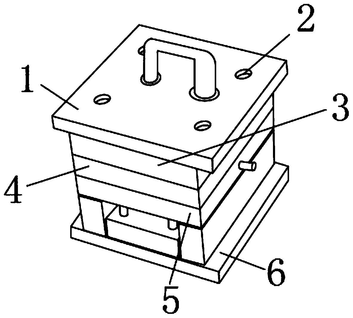
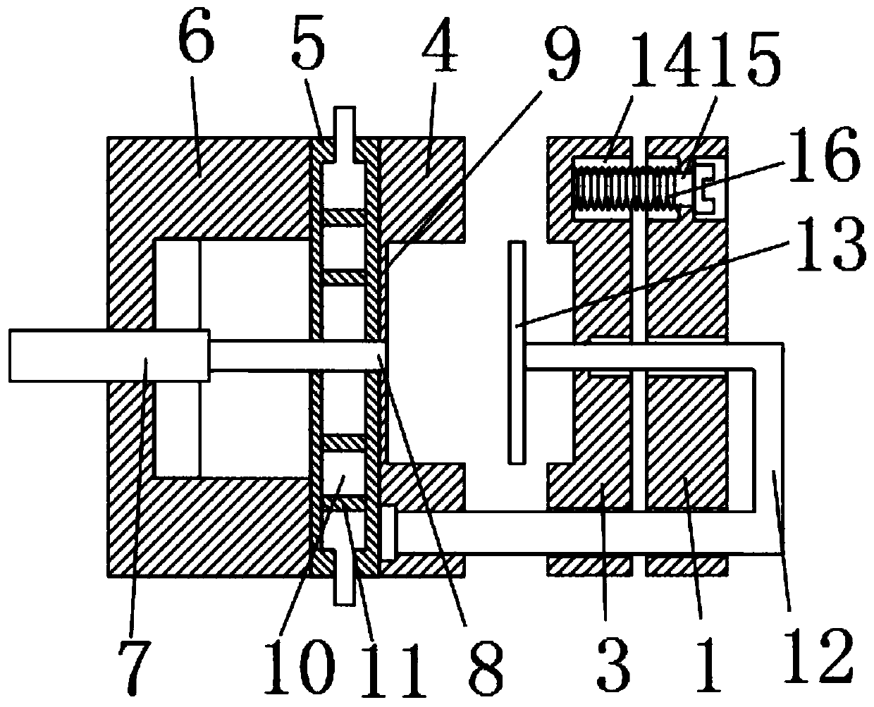
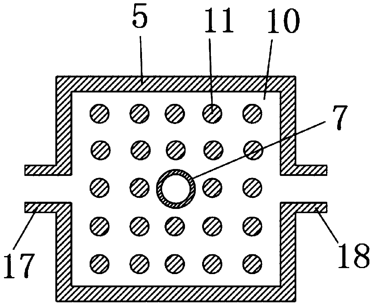
The invention discloses a rapid cooling forming mold. The mold comprises an upper mold base, fixed screw holes are formed in the positions, close to the four corners, of the upper surface of the upper mold base, a first forming mold block is fixedly mounted on the lower surface of the upper mold base, a second forming mold block is movably mounted on the lower surface of the first forming mold block, a cooling mold block is fixedly mounted on the lower surface of the second forming mold block, a lower mold base is fixedly mounted on the lower surface of the cooling mold block, a filling guide pipe is fixedly is fixedly mounted at the position, penetrating through the middles of the cooling mold block and the second forming mold block, of the middle of the lower mold base, and a nozzle is formed in one end of the filling guide pipe. According to the rapid cooling forming mold, the cooling mold block and a discharging guide column are arranged, cooling can be rapidly finished, work efficiency is improved, a workpiece can be conveniently ejected out, manpower cost is saved, the mold is suitable for different working conditions, and the better use prospects are achieved.

Description

technical field [0001] The invention relates to the field of molds, in particular to a mold for rapid cooling molding. Background technique [0002] The mold is a rapid prototyping engraving tool, which consists of an upper mold base and a lower mold base. The mold is a tool used to make shaped objects. This tool is composed of various parts. Different molds are composed of different parts. It mainly realizes the processing of the shape of the object through the change of the physical state of the formed material. It has a good engraving effect and low production cost, and is widely used in various fields; the existing molds have certain disadvantages when used. The internal workpiece cannot be cooled and formed quickly, and the internal workpiece cannot be ejected more conveniently. Generally, it is manually disassembled, or it needs to be ejected by other power devices. Therefore, we propose a rapid cooling molding mold. Contents of the invention [0003] The main purp...

Claims


Application Information

Patent Timeline
Patent Type & Authority Applications(China)
IPC IPC(8): B29C33/04B29C33/44
CPCB29C33/04B29C33/44
Inventor 胡威威李伟刘丁孔谭蕴赵丰停
Owner GUIZHOU UNIV
Learn More