
Clamping and moving mechanism for angle iron processing

A technology of moving mechanism and angle steel, which is applied in the direction of metal processing machine parts, metal processing equipment, clamping, etc., can solve the problems of low efficiency, heavy manual labor, poor effect, etc., and achieve good effect, convenient movement, and convenient manual or The effect of mechanical punching

Active Publication Date: 2019-09-27
台州市鑫屏机电有限公司
View PDF6 Cites 2 Cited by
  • Summary
  • Abstract
  • Description
  • Claims
  • Application Information

AI Technical Summary

Problems solved by technology

[0003] The existing drilling method is manual, which needs to manually move the drilling equipment of the drilling machine to automatically punch holes and manually move the angle steel. After drilling a hole, it needs to manually remove the fixed block fixed by the angle steel, and then move the angle steel position, so that the position that needs to be drilled in the future faces the drill bit, and then the fixing block is fixed, which has low efficiency, poor effect, and a large amount of manual labor.

Method used


Image

  • Clamping and moving mechanism for angle iron processing
  • Clamping and moving mechanism for angle iron processing
  • Clamping and moving mechanism for angle iron processing

Examples


Embodiment Construction

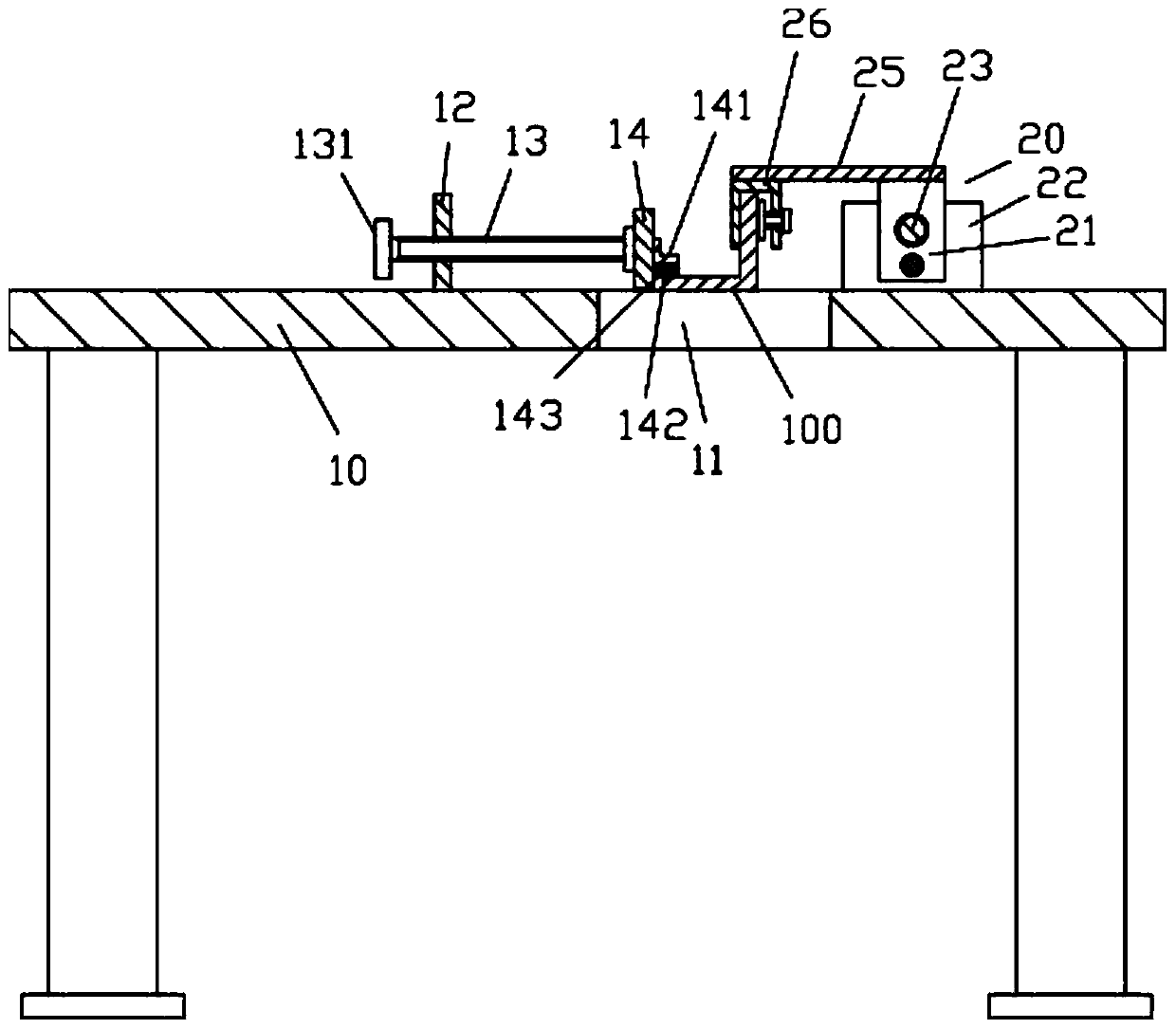
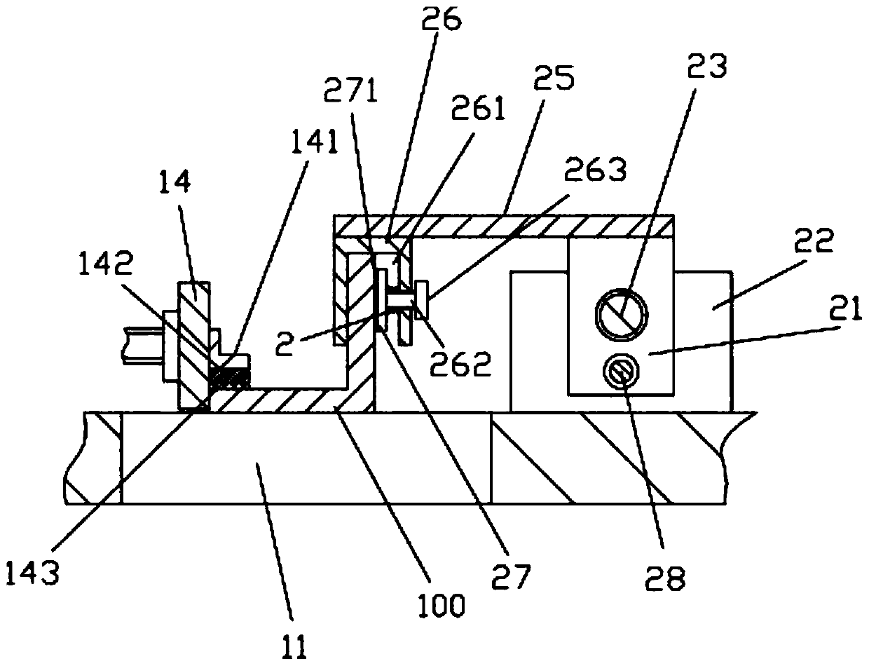
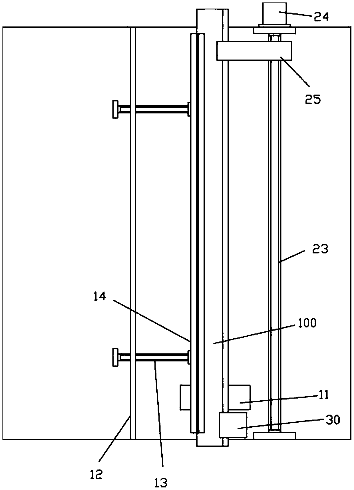
[0022] Examples, see e.g. Figure 1 to Figure 4 As shown, a clamping and moving mechanism for angle steel processing includes a frame 10, and the middle part of the front part of the top plate of the frame 10 has a through groove 11 for processing;

[0023] The left top surface of the top plate of the frame 10 is fixed with a side support plate 12, and the front and rear portions of the left side wall of the side support plate 12 are all screwed with adjusting screw rods 13, and the right ends of the two adjusting screw rods 13 pass through bearings. Hinged on the left side baffle plate 14, the left ends of the two adjusting screw rods 13 extend out of the side support plate 12 and are fixed with a rotating part 131, and the right side top surface of the top plate of the frame 10 is equipped with a clamping and moving mechanism 20;

[0024] The angle steel 100 to be processed is placed on the top surface of the top plate of the frame 10, the left side wall of the horizontal bo...


PUM


Abstract

The invention discloses a clamping and moving mechanism for angle iron processing. The clamping and moving mechanism for angle iron processing comprises a rack. A straight slot for processing is formed in the middle of the front part of a top plate of the rack; and a side supporting plate is fixed to the top surface of the left side of the top plate of the rack, adjusting screws are in screw joint to the front part and the back part of the left side wall of the side supporting plate, the right ends of the two adjusting screws are hinged to a left side baffle plate through a bearing, the left ends of the two adjusting screws stretch out of the side supporting plate and rotating parts are fixed to the left ends of the two adjusting screws, and a clamping and moving mechanism is mounted on the top surface of the right side of the top plate of the rack. The clamping and moving mechanism for angle iron processing can clamp to-be-processed angle iron automatically and move the to-be-processed angle iron automatically, so that a position, needed to be perforated, of the to-be-processed angle iron is moved right above the straight slot for processing, the to-be-processed angle is perforated manually or mechanically conveniently, and the to-be-processed angle is convenient to move, and the clamping and moving mechanism for angle iron processing is good in effect.

Description

technical field [0001] The invention relates to the technical field of fan processing equipment, and more specifically relates to a clamping and moving mechanism for angle steel processing. Background technique [0002] When the existing fan is installed, the outer wall of the volute generally needs to be installed on a bracket welded by a plurality of angle steels, and the angle steel is generally formed with a plurality of installation through holes to facilitate its passage through the bolts and the volute. The side wall of the shell is connected, which needs to be drilled on the angle steel in advance; [0003] The existing drilling method is manual, which needs to manually move the drilling equipment of the drilling machine to automatically punch holes and manually move the angle steel. After drilling a hole, it needs to manually remove the fixed block fixed by the angle steel, and then move the angle steel position, so that the position that needs to be drilled in the...

Claims


Application Information

Patent Timeline
IPC IPC(8): B23B41/00B23B47/00B23Q1/25B23Q3/06
CPCB23B41/00B23B47/00B23Q1/25B23Q3/06
Inventor 梁忠义
Owner 台州市鑫屏机电有限公司
Learn More