Multi-angle punching machine

A multi-angle, punching machine technology, used in metal processing equipment, feeding devices, manufacturing tools, etc., can solve problems such as affecting punching accuracy, complex procedures, affecting raw material positioning accuracy, etc., to improve work efficiency and simplify feeding. process, the effect of eliminating the sawing process

Pending Publication Date: 2019-09-27
张家港市诺恩机械有限公司
View PDF0 Cites 2 Cited by
  • Summary
  • Abstract
  • Description
  • Claims
  • Application Information

AI Technical Summary

Problems solved by technology

[0002] At present, the existing punching machines can only punch in one direction (mostly punching from top to bottom). hole), it needs multiple feeds to complete the multi-faceted punching work (for the square tube after punching one face or two opposite faces, take out the raw material, turn it over at a certain angle, and then feed again, and then proceed to other surface punching work); at the same time, during the punching operation, the feeding mechanism needs to hold the end of the raw material and intermittently feed the material to the punching station. Since the end of the raw material is clamped, it cannot Realize the direct punching of the end of the raw material. In order to meet the needs of the end punching, the raw material to be punched needs to be longer than the finished material (after the raw material is punched), and the long part is clamped by the feeding mechanism. After the punching is completed, The part sawing that grows is come off (sawing scrap), to meet the regulation of finished product, adopts above-mentioned punching machine to have following defect:
[0003] 1. The process is complicated and the production efficiency is low;
[0004] 2. Multiple feedings in the punching stage will affect the positioning accuracy of the raw material, which in turn will affect the punching accuracy;
[0005] 3. Due to the existence of sawing waste, it will not only cause waste of raw materials, but also cause sawing errors, and the accuracy of finished materials is not guaranteed

Method used


Image

  • Multi-angle punching machine
  • Multi-angle punching machine
  • Multi-angle punching machine

Examples


Embodiment Construction

[0042] The present invention will be described in further detail below through specific examples.

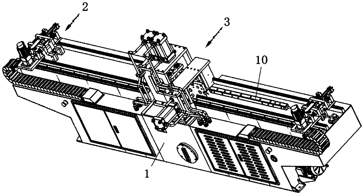
[0043] For ease of description, in this solution, the raw material 10 is a square tube, but the square tube is not limited thereto.

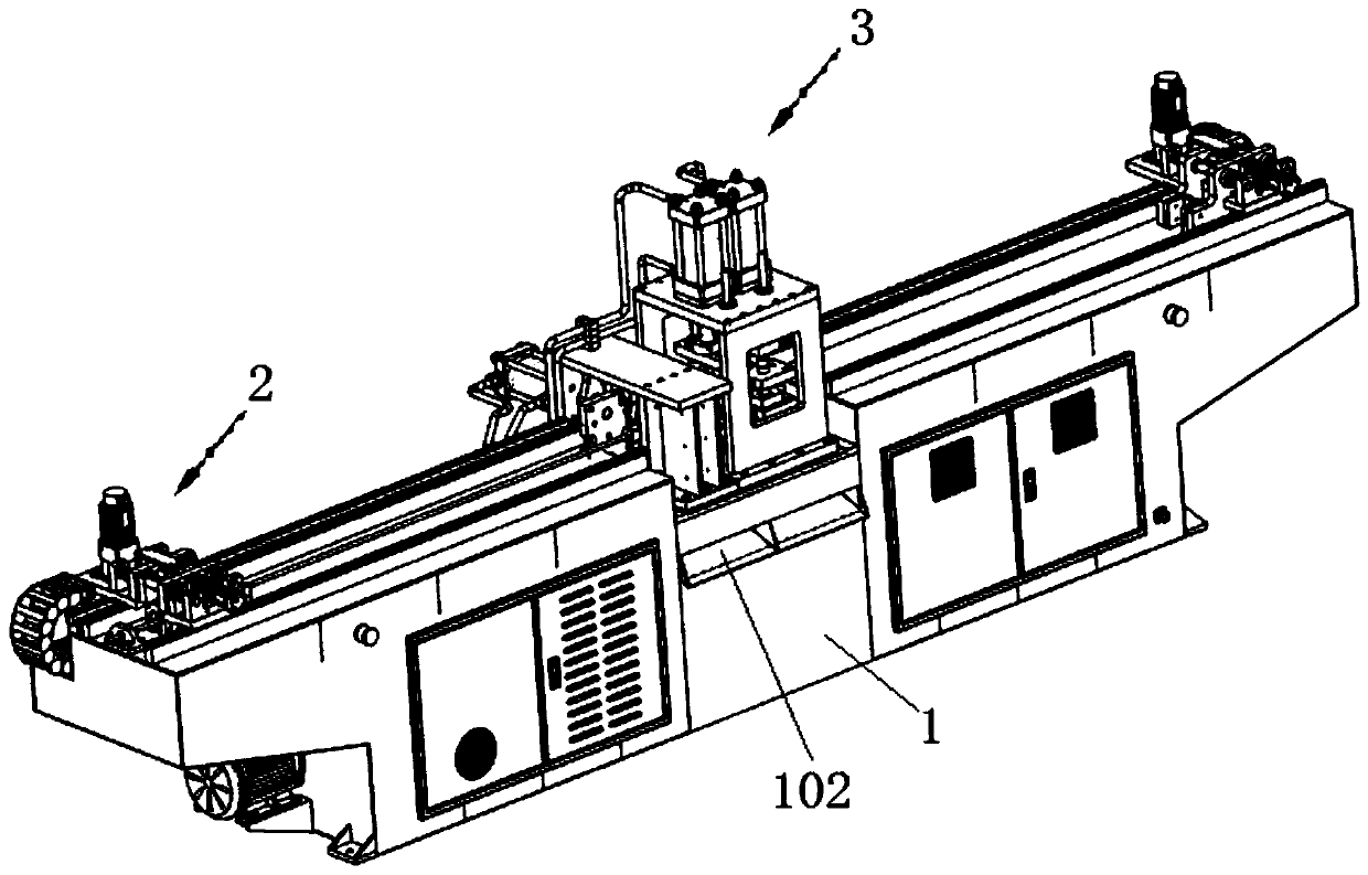
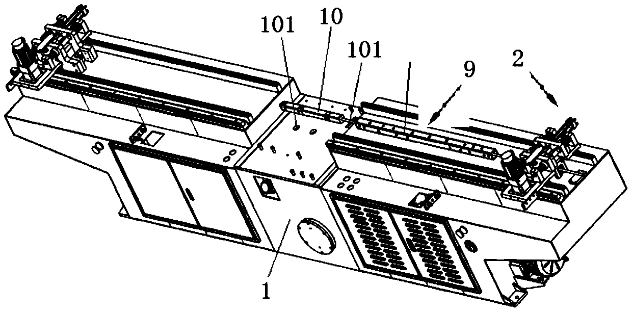
[0044] Such as Figure 1 to Figure 3 Commonly shown, a multi-angle punching machine, including a body 1, the two ends of the body 1 are slidingly installed with a raw material clamping and feeding mechanism 2, and the body 1 between the two raw material clamping and feeding mechanisms 2 is equipped with multiple Angle punching head 3, the multi-angle punching head 3 is provided with a raw material positioning and guiding mechanism 4, the raw material positioning and guiding mechanism 4 is provided with a mandrel 5, one end of the mandrel 5 is connected to the frame 1 A mandrel support mechanism 9 is provided between them, and the mandrel support mechanism 9 passes through a raw material clamping and feeding mechanism 2.

[0045] Such as Figure...


PUM


Abstract

The invention discloses a multi-angle punching machine which comprises a machine body, wherein raw material clamping and feeding mechanisms are installed on two ends of the machine body in a sliding manner; a multi-angle punching machine head is disposed on the machine body located between the two raw material clamping and feeding mechanism; a raw material positioning and transport guiding mechanism is disposed inside the multi-angle punching machine head; a core rod is disposed inside the raw material positioning and transport guiding mechanism; a core rod supporting mechanism is disposed between one end of the core rod and a rack; and the core rod supporting mechanism passes through one of the raw material clamping and feeding mechanism. The machine has the beneficial effects that multi-direction punching of a raw material can be completed with one time of feeding, feeding of multiple times is not needed, feeding processes are simplified, working efficiency is increased, and precision of positioning and punching is high; and meanwhile, online punching of a clamped area of the raw material is realized through alternate clamping of the raw material by the two raw material clamping and feeding mechanism, the raw material do not need to be sawn and cut in comparison with traditional tools, the raw material is not wasted, processes of sawing and cutting are saved, production efficiency of a finished material is greatly increased, and processing precision of the finished material is effectively ensured.

Description

technical field [0001] The invention belongs to the technical field of punching equipment, in particular to a multi-angle punching machine. Background technique [0002] At present, the existing punching machines can only punch in one direction (mostly punching from top to bottom). hole), it needs multiple feeds to complete the multi-faceted punching work (for the square tube after punching one face or two opposite faces, take out the raw material, turn it over at a certain angle, and then feed again, and then proceed to other surface punching work); at the same time, during the punching operation, the feeding mechanism needs to hold the end of the raw material and intermittently feed the material to the punching station. Since the end of the raw material is clamped, it cannot Realize the direct punching of the end of the raw material. In order to meet the needs of the end punching, the raw material to be punched needs to be longer than the finished material (after the raw ...

Claims


Application Information

Patent Timeline
Patent Type & Authority Applications(China)
IPC IPC(8): B21D28/28B21D43/10
CPCB21D28/28B21D43/006B21D43/10
Inventor 何峰
Owner 张家港市诺恩机械有限公司
Why Eureka
Try Eureka