Polarizing fundus camera for effectively suppressing internal reflection

A technology of internal reflection and camera, applied in ophthalmoscope, optics, application, etc., can solve the problems of expensive devices, achieve low cost, reduce diagnosis and treatment costs, and reduce production costs

Inactive Publication Date: 2019-09-20
ALINSIGHT INC
View PDF12 Cites 0 Cited by
  • Summary
  • Abstract
  • Description
  • Claims
  • Application Information

AI Technical Summary

Problems solved by technology

(iii) Most importantly, there are few popular imaging devices that can capture near-infrared rays with high resolution, and even the near-infrared imaging devices with reduced resolution are extremely expensive
As a result, such devices are only available in large, large hospitals, and many patients are diagnosed and treated for the diseases mentioned above only in secondary or tertiary hospitals

Method used


Image

  • Polarizing fundus camera for effectively suppressing internal reflection
  • Polarizing fundus camera for effectively suppressing internal reflection
  • Polarizing fundus camera for effectively suppressing internal reflection

Examples


Embodiment Construction

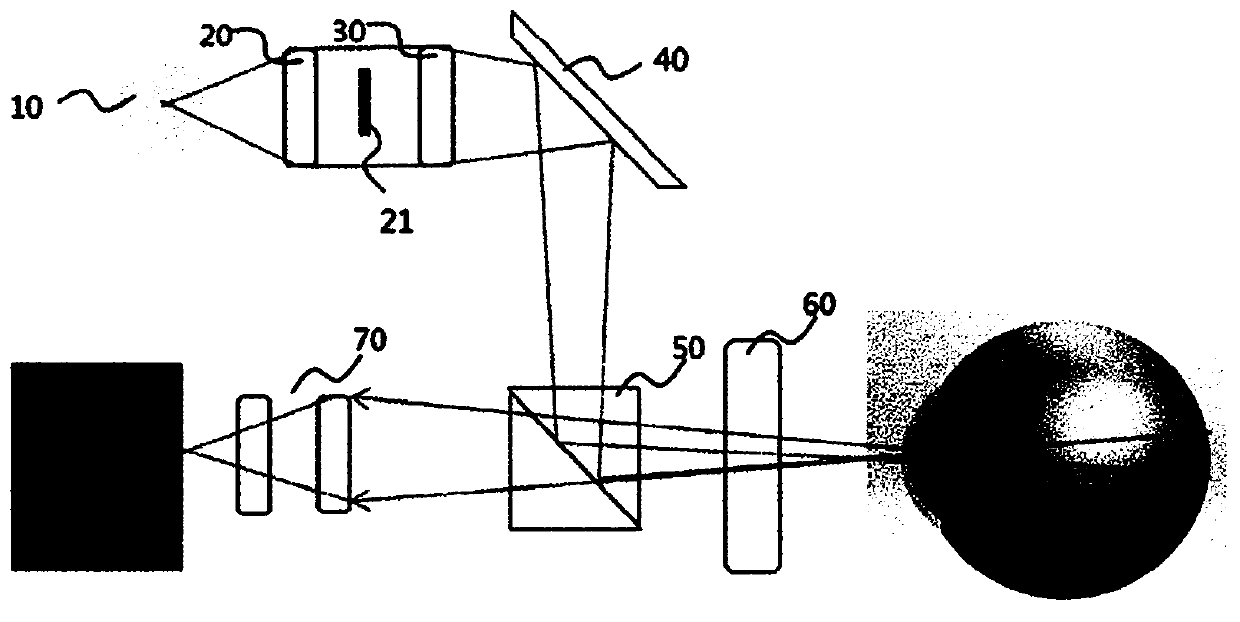
[0044] The present invention is a kind of fundus camera which is one of ophthalmic examination and diagnosis devices. If the conventional color fundus camera is a device that can pass through the visible light band (400nm-640nm) and have a wavelength greater than 640nm, and then present retinal lesions and diagnose retinal diseases The choroidography fundus camera and its components are used to photograph the choroidal blood vessels and choroidal lesions behind the retina together with near-infrared rays.

[0045]Specific matters including the above-mentioned technical problems of the present invention, solutions to the problems, and effects of the invention are included in one embodiment described below and the drawings. Reference and attachment Figure 1 With an embodiment described in detail later, the advantages, features and methods for realizing the present invention will become more clear.

[0046] like figure 1 As shown, the polarized fundus camera for effectively s...


PUM


Abstract

The present invention is a type of fundus camera which is one of eye examination and diagnosis equipment. A conventional color fundus camera is equipment for illuminating retinas with light of the visible band (400-640 nm), and then showing retinal lesions and diagnosing retinal diseases. The present invention relates to: a choroidal imaging fundus camera capable of photographing both a choroidal vessel and a choroidal lesion at the back of the retina with near-infrared rays having a wavelength longer than 640 nm; and a device comprising the same. A polarizing fundus camera for effectively suppressing internal reflection, of the present invention, comprises: a lighting part (10) for emitting light; a diffusion lens (20) for diffusing the light incident from the lighting part (10); a lighting lens (30) for emitting, at a predetermined emission angle, the light incident from the diffusion lens (20); a mirror (40) for reflecting the light incident from the lighting lens (30); a polarizing beam splitter (50) allowing a P-polarized light to pass therethrough and an S-polarized light to be reflected in the light incident from the mirror (40); an objective lens (60) for magnifying an image of the fundus of the eye, which has been formed by the light incident from the polarizing beam splitter (50); a short-range eyepiece (70) for reducing the image, of the fundus of the eye, having been magnified by means of the objective lens (60); a linear polarizing filter (80) allowing only the P-polarized light to pass therethrough; a narrow-band optical filter (90) filtering, from the light having passed through linear polarizing filter, the light having a band of 12 nm or less and emitted from the polarizing beam splitter (50); and an imaging device (100) using the light having passed through the narrow-band optical filter (90) so as to convert the same into an electrical signal and acquire an image, wherein the linear polarizing filter (80) respectively has a first linear polarizing filter (81) provided between the lighting part (10) and the polarizing beam splitter (50), and a second linear polarizing filter (82) provided between the polarizing beam splitter (50) and the short-range eyepiece (70).

Description

technical field [0001] The present invention relates to a fundus camera which is one of ophthalmic diagnostic devices. If the conventional color fundus camera is a device for diagnosing retinal diseases by contrasting the retina with light in the visible light band (400nm to 640nm), the present invention relates to a device capable of photographing the rear side of the retina together with near-infrared rays with a wavelength greater than 640nm A choroidographic fundus camera for choroidal vascular and choroidal lesions and devices constituting it. Background technique [0002] Conventional fundus cameras use a method in which a light source mainly in the visible light band creates a shadow on the fundus, and the reflected fundus shadow is stored in an image recording device to form an image. This method has been widely used until now, however, recently, many diseases that invade choroidal vessels and choroidal capillaries such as senile AMD, hereditary macular degeneration...

Claims


Application Information

Patent Timeline
Patent Type & Authority Applications(China)
IPC IPC(8): A61B3/14A61B5/00A61B3/12G02B27/28A61B3/00
CPCA61B3/12A61B5/00G02B27/283G02B27/0018A61B3/0008A61B3/156A61B3/14G02B27/28A61B3/112
Inventor 权汉祚朴建炯
Owner ALINSIGHT INC
Why Eureka
Try Eureka