
Intelligent ammeter

A technology of smart electric meters and electric meters, applied in the direction of measuring electric variables, measuring devices, instruments, etc., can solve the problems of reduced service life, damage, and temperature rise of electric meters, and achieve the effect of preventing pollution damage, preventing damage, and simple equipment structure

Inactive Publication Date: 2019-09-20
胡云鑫
View PDF0 Cites 2 Cited by
  • Summary
  • Abstract
  • Description
  • Claims
  • Application Information

AI Technical Summary

Problems solved by technology

[0002] The ammeter is a device used to measure the amount of electricity consumed by the user. The ammeter is overheated during use, and under the action of sunlight and high temperature, the temperature of the components inside the meter is likely to rise, making the meter run inaccurately, resulting in user More losses. At the same time, because the ammeter is directly connected to the circuit and is in the open state, in some emergency situations, such as: lightning, fire and earthquake, etc., the ammeter will be disconnected, which will cause high temperature spontaneous combustion. This endangers the personal safety of personnel to a great extent, and reduces the service life of the ammeter, makes the ammeter more prone to spontaneous combustion and causes damage, greatly reduces the practicability of the ammeter, and due to the existing fire extinguishing technology, the ammeter It is not possible to use foam fire extinguishing method to extinguish the fire related components of the meter. This requires the use of dry powder and other dry particles to extinguish the fire of the meter. However, since the meter can also be used after the fire is extinguished, it is not necessary to burn the meter if it is directly sprayed with dry powder. Partial isolation will fill the entire meter with dry powder, damage other components of the meter and make it impossible to use it again, which greatly violates the principle of recyclable items and increases the consumption and loss of equipment

Method used


Image

  • Intelligent ammeter
  • Intelligent ammeter
  • Intelligent ammeter

Examples


Embodiment Construction

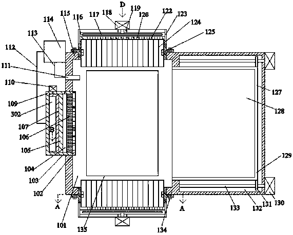
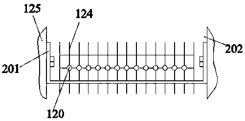
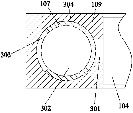
[0024] Such as Figure 1-Figure 5 As shown, the present invention is described in detail. For the convenience of description, the orientations mentioned below are now stipulated as follows: figure 1 The up, down, left, right, front and back directions of the projection relationship are consistent. A smart meter of the present invention includes an installation box 115, and an inner cavity 101 is arranged inside the inner cavity 101, and an electric meter 135 is installed inside the inner cavity 101. The upper and lower sides of the chamber 101 are provided with vertically symmetrical heat sinks that dissipate heat from the electric meter 135, the left side of the inner chamber 101 is provided with a fire extinguishing device for extinguishing the electric meter 135, and the right side of the inner chamber 101 is provided with a Prevent the fire extinguishing powder from polluting the shielding device of the electric meter 135, so that the device can be used for efficient heat ...


PUM


Abstract

The invention discloses an intelligent ammeter. The intelligent ammeter comprises an installation box, wherein an inner cavity is arranged in the installation box, an ammeter is arranged in the inner cavity, heat dissipation devices which are vertically symmetrical and are used for dissipating heat of the ammeter are arranged on the upper side and the lower side of the inner cavity, a fire extinguishing device used for extinguishing fire of the ammeter is arranged on the left side of the inner cavity, and a shielding device used for preventing powder from extinguishing fire from polluting the ammeter is arranged on the right side of the inner cavity. The intelligent ammeter is simple in structure, the aluminum sheet and the copper pipe are used for radiating heat under the driving of a hot air fan, the ammeter is sealed and protected, the fire extinguishing powder is reused for efficiently extinguishing fire, damage to other parts in the fire extinguishing process is avoided, and the powder is prevented from polluting and damaging the device.

Description

technical field [0001] The invention relates to the technical field of electric power technology equipment, in particular to a smart electric meter. Background technique [0002] The ammeter is a device used to measure the amount of electricity consumed by the user. The ammeter is overheated during use, and under the action of sunlight and high temperature, the temperature of the components inside the meter is likely to rise, making the meter run inaccurately, resulting in user More losses. At the same time, because the ammeter is directly connected to the circuit and is in a state of communication, in some emergency situations, such as: lightning, fire and earthquake, etc., the ammeter will be disconnected, which will cause high temperature spontaneous combustion. This endangers the personal safety of personnel to a large extent, and reduces the service life of the ammeter, makes the ammeter more prone to spontaneous combustion and causes damage, greatly reduces the practic...

Claims


Application Information

Patent Timeline
Patent Type & Authority Applications(China)
IPC IPC(8): G01R11/04G01R11/02A62C3/16H05K7/20
CPCA62C3/16G01R11/02G01R11/04H05K7/2039
Inventor 不公告发明人
Owner 胡云鑫
Learn More