
Tape indentation detecting machine

A detection machine and braiding technology, which is applied in the direction of measuring devices, optical testing of flaws/defects, and material analysis through optical means, and can solve problems such as low detection efficiency, manual detection, and low detection accuracy

Inactive Publication Date: 2019-09-20
东莞市华越半导体技术股份有限公司
View PDF0 Cites 0 Cited by
  • Summary
  • Abstract
  • Description
  • Claims
  • Application Information

AI Technical Summary

Problems solved by technology

[0002] IC electronic components are packaged by carrier tape and braid. Traditionally, the detection of hot-melt indentation on the carrier tape and braid of packaged IC electronic components is observed and judged by human eyes, that is, its Observe and judge whether the hot-melt indentation of the carrier tape and the braid is uniform, check whether the hot-melt indentation of the carrier tape and the braid is firm, check whether the hot-melt indentation of the carrier tape and the braid is intermittent, etc. The method of human eye detection to judge whether the hot-melt indentation of carrier tape and braid is qualified not only has the disadvantages of low detection efficiency, low detection accuracy and poor detection effect, but also leads to high labor intensity for workers and high labor costs for enterprises. Meet the requirements of large-scale mass production and automated production of enterprises
In order to overcome the problem of manual detection of IC electronic components, the applicant has proposed a Chinese invention patent with the patent number "2019105570108" and a Chinese utility patent with the patent number "2019209656279". It cannot control the belt transmission mechanism to stop operating according to the detection data and detection signal, so that the operator can quickly find the root of the problem and troubleshoot in time

Method used

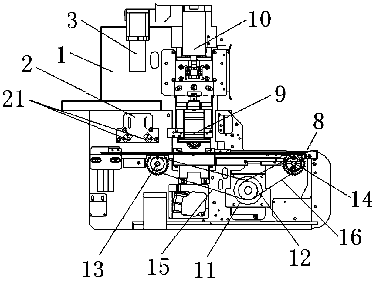

Image

  • Tape indentation detecting machine
  • Tape indentation detecting machine
  • Tape indentation detecting machine

Examples


Embodiment Construction

[0016] In order to facilitate the understanding of the present invention, the present invention will be described more fully below with reference to the associated drawings. Preferred embodiments of the invention are shown in the accompanying drawings. However, the present invention can be embodied in many different forms and is not limited to the embodiments described herein. On the contrary, the purpose of providing these embodiments is to make the disclosure of the present invention more thorough and comprehensive.

[0017] Unless otherwise defined, all technical and scientific terms used herein have the same meaning as commonly understood by one of ordinary skill in the technical field of the invention.

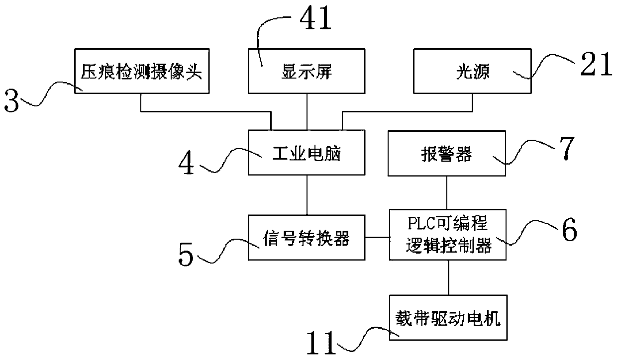
[0018] In this example, refer to Figure 1 to Figure 3 As shown, a kind of braiding indentation detection machine of the present invention includes a carrier tape transmission mechanism, a frame 1 is arranged on the rear side of the carrier tape transmission mechanism, ...


PUM


Abstract

The invention discloses a tape indentation detecting machine. The detecting machine includes a carrier tape transmission mechanism, a frame, a light source support, light sources, an indentation detection camera, an industrial computer, a signal converter, a PLC (programmable logic controller), a carrier tape, a tape heat-sealing soldering iron block, a tape heat-sealing air cylinder, etc. Through the detecting machine, automatic detection on a tape and the carrier tape accomplishing hot melt indentation can be realized, the detecting machine can control the carrier tape transmission mechanism to stop running according to detection results, operators can conveniently and timely check and inspect unqualified tapes and carrier tapes, so that the operators can conveniently find problems and rapidly find the sources of the problems, and therefore, faults can be effectively eliminated, parameters operated by each part can be re-adjusted and controlled, the phenomenon of the follow-up appearance of unqualified hot melt indentation can be effectively avoided, the rate of finished products of hot melted tapes and carrier tapes can be increased, detection efficiency can be enhanced, thus, the detecting machine is high in detection precision, good in detection effect, and more convenient and faster in usage.

Description

technical field [0001] The invention relates to a braided tape indentation detection machine. Background technique [0002] IC electronic components are packaged by carrier tape and braid. Traditionally, the detection of hot-melt indentation on the carrier tape and braid of packaged IC electronic components is observed and judged by human eyes, that is, its Observe and judge whether the hot-melt indentation of the carrier tape and the braid is uniform, check whether the hot-melt indentation of the carrier tape and the braid is firm, check whether the hot-melt indentation of the carrier tape and the braid is intermittent, etc. The method of human eye detection to judge whether the hot-melt indentation of carrier tape and braid is qualified not only has the disadvantages of low detection efficiency, low detection accuracy and poor detection effect, but also leads to high labor intensity for workers and high labor costs for enterprises. It meets the requirements of large-scale...

Claims


Application Information

Patent Timeline
IPC IPC(8): G01N21/892G01N21/89G01N21/88
CPCG01N21/8851G01N21/8914G01N21/892G01N2021/8887G01N2021/8924G01N2201/0484
Inventor 谢国清
Owner 东莞市华越半导体技术股份有限公司
Learn More