
Electromagnetic loading device and loading method used for reliability testing of numerically-controlled machine tool

A technology of CNC machine tools and loading devices, which is applied in the direction of measuring devices, testing of mechanical parts, testing of machine/structural parts, etc., can solve problems such as large vibration, complex loading device structure, small load range, etc., and achieve small vibration and control Convenient, wide-ranging effect loading

Inactive Publication Date: 2019-09-20
BEIHANG UNIV
View PDF5 Cites 3 Cited by
  • Summary
  • Abstract
  • Description
  • Claims
  • Application Information

AI Technical Summary

Problems solved by technology

[0006] The purpose of the present invention is to at least solve the problems of complex structure, small load range and large vibration of the existing loading device, which is achieved by the following technical solutions:

Method used


Image

  • Electromagnetic loading device and loading method used for reliability testing of numerically-controlled machine tool
  • Electromagnetic loading device and loading method used for reliability testing of numerically-controlled machine tool
  • Electromagnetic loading device and loading method used for reliability testing of numerically-controlled machine tool

Examples


Embodiment Construction

[0038] Exemplary embodiments of the present disclosure will be described in more detail below with reference to the accompanying drawings. Although exemplary embodiments of the present disclosure are shown in the drawings, it should be understood that the present disclosure may be embodied in various forms and should not be limited by the embodiments set forth herein. Rather, these embodiments are provided for more thorough understanding of the present disclosure and to fully convey the scope of the present disclosure to those skilled in the art.

[0039] It should be understood that the terminology used herein is for the purpose of describing particular example embodiments only and is not intended to be limiting. As used herein, the singular forms "a", "an" and "the" may also be meant to include the plural forms unless the context clearly dictates otherwise. The terms "comprising", "comprising", "containing" and "having" are inclusive and thus indicate the presence of stated...


PUM


Abstract

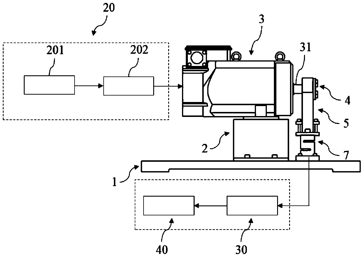
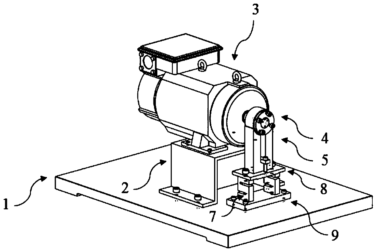
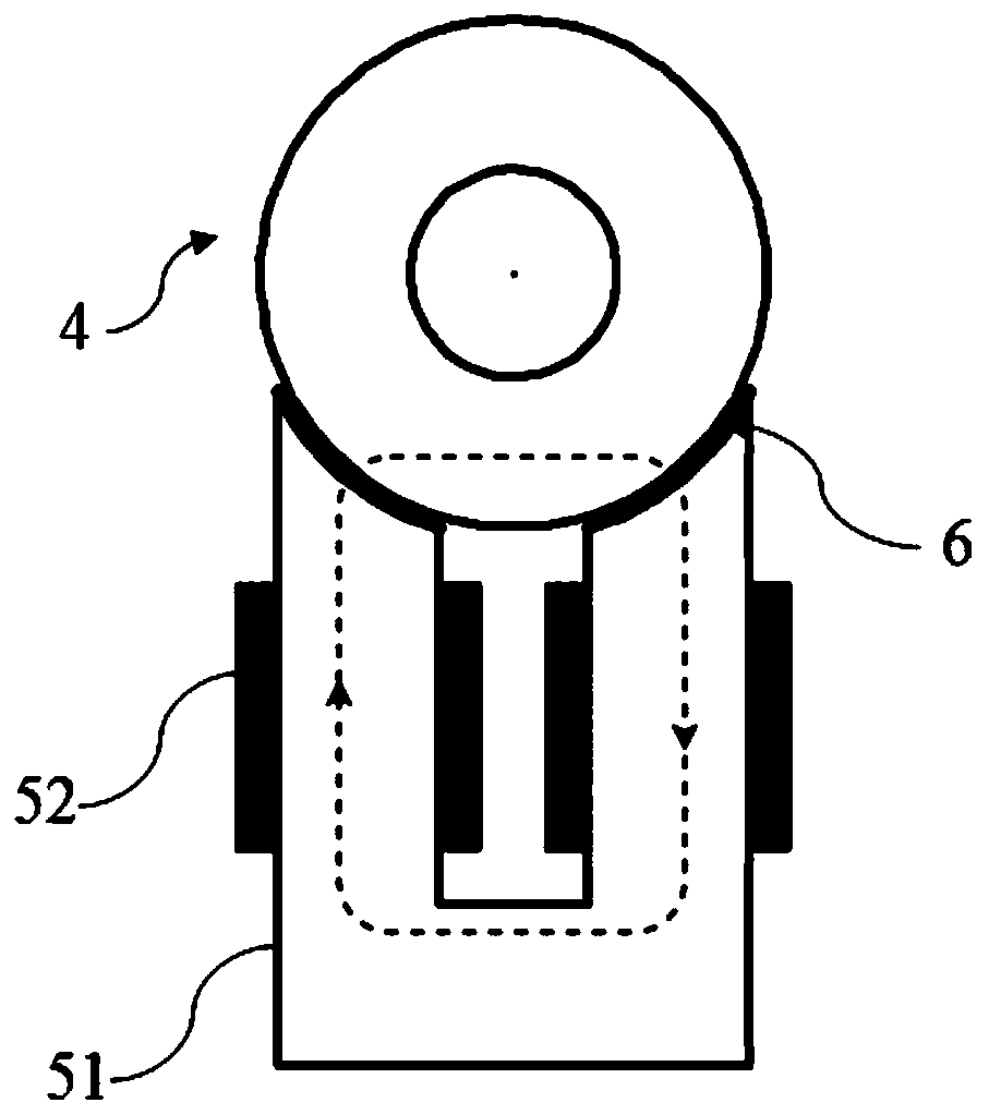
The invention provides an electromagnetic loading device and a loading method used for reliability testing of a numerically-controlled machine tool. The electromagnetic loading device comprises a bottom plate, a motor installed on the bottom plate through a motor support seat, a loading unit connected to a motor main shaft of the motor, and a detecting unit connected to the loading unit. The loading unit comprises a load disk and an electromagnet. The load disk is coaxially connected to an output end of the motor main shaft. The electromagnet is installed below the load disk. A certain air gap is arranged between an end surface of the electromagnet and a circumferential wall surface of the load disk. The detection unit includes an S-type force sensor for detecting a load applied to the motor main shaft and a data acquisition unit which is electrically connected or forms signal connection with the S-type force sensor. In the invention, an electromagnetic principle is used, the load disk is placed in a magnetic field generated by the electromagnet to form an electromagnetic force, a working load received by the motor main shaft under an actual working condition is simulated, a loading effect is good, a loading range is wide, and there is no friction, small vibration and convenient control during a loading process.

Description

technical field [0001] The invention relates to the technical field of life testing of mechanical equipment, in particular to an electromagnetic loading device and a loading method for reliability testing of numerically controlled machine tools. Background technique [0002] The development level of CNC machine tools is a direct reflection of a country's industrial development level and comprehensive national strength. The CNC system is the core component of CNC machine tools and is called the "brain" of machine tools. Its reliability is the main factor restricting the development of high-end CNC machine tools in my country. Due to the long life and high reliability of the CNC system and its key component drive units, the loading and reliability test methods of the CNC system and its drive units should be studied without changing the failure mode and mechanism of the CNC system. , an accelerated life test is essential. However, the further in-depth research of accelerated l...

Claims


Application Information

Patent Timeline
Patent Type & Authority Applications(China)
IPC IPC(8): G01M13/00
CPCG01M13/00
Inventor 彭翀
Owner BEIHANG UNIV
Learn More