Capillary water seal device for fan and water seal method of capillary water seal device

A technology of capillary water and fan, which is applied in space heating and ventilation details, heating methods, mechanical equipment, etc., can solve the problems of large space occupation, difficult disassembly and cleaning, and cumbersome problems, so as to prevent air from crossing and preventing air from entering the fan system , to ensure the effect of safe operation

Inactive Publication Date: 2019-09-20
SUZHOU NUCLEAR POWER RES INST +2
View PDF7 Cites 2 Cited by
  • Summary
  • Abstract
  • Description
  • Claims
  • Application Information

AI Technical Summary

Problems solved by technology

[0003] At present, most of the existing drainage and gas blocking devices are pipe-type water sealing devices (structures such as Figure 7 The schematic diagram of the connection structure between the condensate pan 9 and the condensate pipe fitting 20), a small part is other types of water seal devices (non-pipeline), and the installation of the pipeline type water seal device needs to go through the following process: Calculating the height of the water seal—— Prefabricate the pipeline according to the height of the water seal - install the pipe fittings on site. Therefore, the pipeline water seal device has the following disadvantages: 1. Design and calculation are required for each installation; 2. The process of prefabricating the pipeline on site (to ensure that the height of the water seal is consistent with the design ) is cumbersome; 3. It is not easy to disassemble and clean
At the same time, the existing non-pipeline water seal device has a complex structure and takes up a lot of space, so it cannot be applied to areas with narrow spaces

Method used


Image

  • Capillary water seal device for fan and water seal method of capillary water seal device
  • Capillary water seal device for fan and water seal method of capillary water seal device
  • Capillary water seal device for fan and water seal method of capillary water seal device

Examples


Embodiment Construction

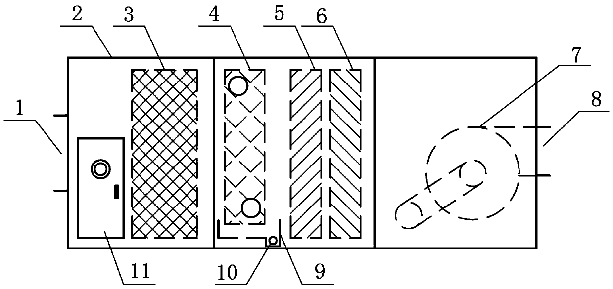
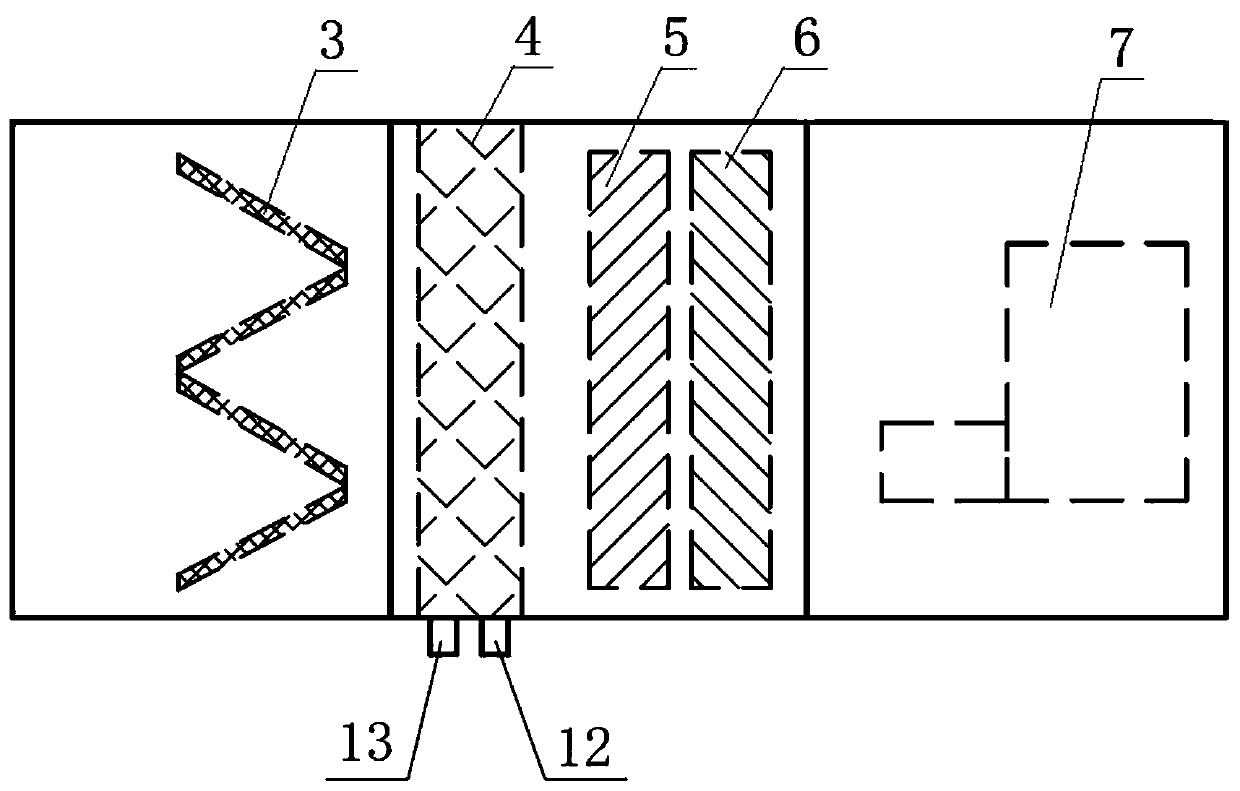
[0024] Compared with the prior art, the technical problem to be solved by the present invention is: most of the existing drainage and gas blocking devices are pipeline type water sealing devices, and a small part is other types of water sealing devices (non-pipeline); The traditional water seal device has the problems of cumbersome installation and difficult disassembly. The existing non-pipeline water seal device has a complex structure and takes up a lot of space, so it cannot be applied to areas with narrow spaces. In view of the above problems, the idea of ​​the present invention is: the present invention is based on the capillary phenomenon, through (but not limited to) the capillary water seal pipe, the accumulated water in the drain tank and the condensed water in the condensed water pan to form a condensed water seal , Under the action of the condensed water seal, the condensed water generated by heat and humidity exchange is discharged from the equipment, and at the sa...


PUM


Abstract

The invention discloses a capillary water seal device for a fan and a water seal method of the capillary water seal device and relates to a water seal device and method. The capillary water seal device comprises a fan case (2), an air inlet (1), an air outlet (8), a water drainage tank (14) and a capillary water seal pipe (10), wherein a filter (3), a cooling device (4), a humidifying device (5), a heating device (6) and an air pump (7) are arranged in the fan case (2); a condensed water tray (9) which is located in the fan box (2) and used for collecting condensed water is arranged below the cooling device (4); and one end of the capillary water seal pipe (10) is communicated with the condensed water tray (9) through a water-seal water-inlet ring (15), and the other end of the capillary water seal pipe (10) is communicated with the water drainage tank (14) through a water-seal water-outlet ring (16). The invention innovatively applies the capillarity phenomenon to the water seal device, which uses the capillarity phenomenon to balance the difference between internal and external pressures so as to allow condensed water in a unit with negative pressure to flow out smoothly.

Description

technical field [0001] The invention relates to a water sealing device and method, in particular to a capillary water sealing device and a water sealing method for a fan. Background technique [0002] In fans and other equipment, in order to eliminate the condensed water generated by the heat and moisture exchange components, a water receiving tray is often installed under the position of the heat and moisture exchange components and a drain is installed, and a drainage and air blocking device is connected outside the drain to drain the heat and moisture exchange. The condensed water is discharged from the equipment, and at the same time, the air inside and outside the box is prevented from crossing, which not only ensures the safe operation of the equipment, but also prevents polluted air from entering the fan system. This kind of drainage and air blocking device is called condensate water seal. Its working principle is to use the pressure generated by the water column in t...

Claims


Application Information

Patent Timeline
Patent Type & Authority Applications(China)
IPC IPC(8): F24F3/14F24F3/16F24F13/22F24F13/28
CPCF24F3/14F24F13/22F24F13/28F24F8/10F24F8/108
Inventor 陈汉斌湛猛刘阳周均
Owner SUZHOU NUCLEAR POWER RES INST
Why Eureka
Try Eureka