
Mobile lighting device and use method thereof

A technology of mobile lighting and clamping device, applied in the field of machinery, can solve the problems of small lighting range, unchangeable lighting direction, difficult fixing of mobile lighting tools, etc., and achieves the effects of solving fixing difficulties, large free movement range, and quick installation.

Inactive Publication Date: 2019-09-20
SHANGHAI ZHIHUI ELECTRIC APPLIANCE
View PDF6 Cites 1 Cited by
  • Summary
  • Abstract
  • Description
  • Claims
  • Application Information

AI Technical Summary

Problems solved by technology

[0004] The purpose of the present invention is to provide a mobile lighting device and its use method to solve the problems of the current mobile lighting tools such as difficulty in fixing, unchangeable lighting direction and small lighting range.

Method used


Image

  • Mobile lighting device and use method thereof
  • Mobile lighting device and use method thereof
  • Mobile lighting device and use method thereof

Examples


Embodiment 1

[0041] Embodiment 1 provides a mobile lighting device, the structure of which will be described in detail below.

[0042] refer to figure 1 , the mobile lighting device includes a ball lamp 1 and a clamping device 3 , the bottom of the ball lamp 1 is provided with a clip 2 , and the ball lamp 1 is arranged on the clamping device 3 through the clip 2 .

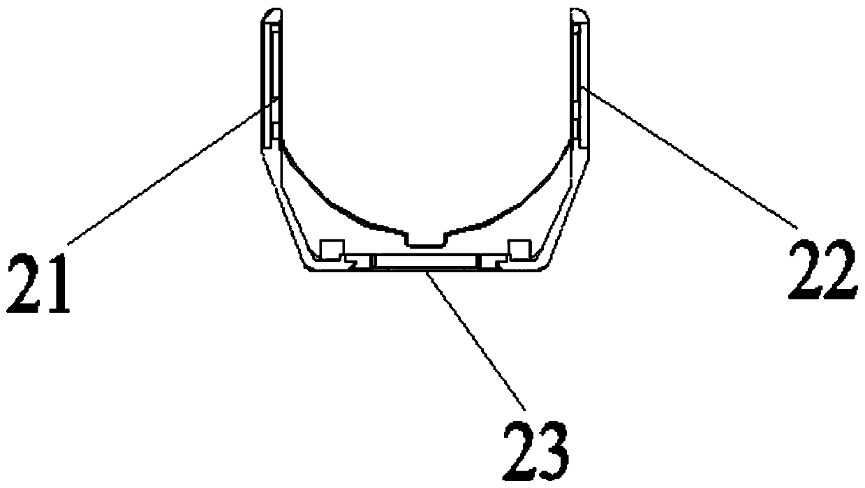
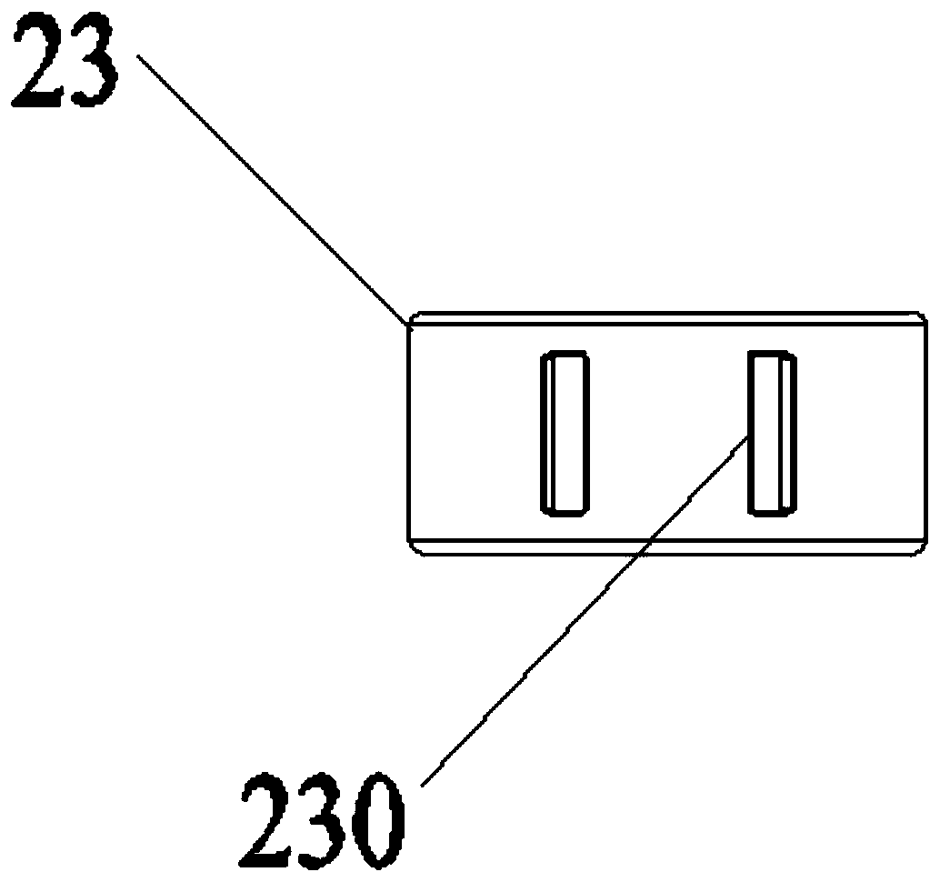
[0043] refer to figure 2 with image 3 , the clip 2 includes a left ear portion 21, a right ear portion 22 and a bottom bracket portion 23, the left ear portion 21 and the right ear portion 22 are respectively arranged at two ends of the bottom bracket portion 23, the The bottom of the bottom support portion 23 is provided with two engaging slots 230 parallel to each other.

[0044] refer to figure 1 , Figure 4 with Figure 5 , the clamping device 3 includes a clamping head 31, a fixed lamp holder 32, a connecting pipe 33 and a rubber pad 344, and the clamping head 31 includes a chuck body 34, a fixing bolt 35 and a cli...

Embodiment 2

[0056] Embodiment 2 provides a method for using a mobile lighting device, using the mobile lighting device provided in Embodiment 1, the method for using the mobile lighting device includes the following steps:

[0057] Assembling the clamping head: use glue to fix the rubber pad 344 on the chuck body 34, screw the fixing bolt 35 into the threaded hole on the clamping head 31, and set the clip 36 on the fixing bolt 35 on;

[0058] Assemble the fixed lamp holder:

[0059] Two groups of the return springs 324 and the control buttons 323 are arranged in the housing 321, so that the two protrusions 320 are respectively installed in the two protrusion holes of the housing 321, and the two protrusions are ensured. The control button 323 is located on the same plane as the two sets of return springs 324;

[0060] The washer 325 is sleeved on the customized nut 326, and the customized nut 326 is vertically arranged in the nut groove;

[0061] The shell cover 321 and the shell botto...


PUM

PropertyMeasurementUnit
Lengthaaaaaaaaaa

Abstract

The invention discloses a mobile lighting device and a use method thereof. The mobile lighting device comprises a circular ball lamp and a clamping device, the clamping device includes a clamping head, a fixed lamp holder and a connecting pipe, the connecting pipe is a rotatable flexible pipe, and the clamping head and the fixed lamp holder are connected through the connecting pipe; and the bottom part of the circular ball lamp is provided with a clamping groove, the fixed lamp holder is provided with a spring pressing mechanism and a bumping, and the bumping is clamped in the clamping groove. The use method comprises the following steps of assembling the clamping head, assembling the fixed lamp holder, installing the connecting pipe, fixing the clamping head and using the circular ball lamp. According to the mobile lighting device and the use method thereof, installation is fast, operation is convenient, various occasions are provided, and application and promotion in markets are worthwhile.

Description

technical field [0001] The invention relates to the field of mechanical technology, in particular to a mobile lighting device and a method for using the same. Background technique [0002] With the improvement of living standards, people have higher and higher requirements for interior decoration. The spherical lamp has a wide range of illumination, so it is used in more and more places. For example, the spherical audio lamps that are common on the market can be rotated 360 degrees without any dead angle for illumination. If the illumination can be moved, the illumination range and the convenience of movement of the spherical lamp can be greatly enhanced. [0003] However, at present, more and more occasions require mobile irradiation of lighting lamps, that is, there are more and more application requirements for mobile lighting fixtures, and the methods and requirements of use are also increasingly diversified. For the convenience of use, it is necessary to clamp the mob...

Claims


Application Information

Patent Timeline
IPC IPC(8): F21L4/00F21V14/02F21V17/12F21V21/088F21V21/14
CPCF21L4/005F21V14/02F21V17/12F21V21/088F21V21/14
Inventor 卞爱霞
Owner SHANGHAI ZHIHUI ELECTRIC APPLIANCE
Learn More