
Hidden handle for vehicle door and vehicle door

A hidden, handle technology, applied in the field of auto parts, can solve problems such as protruding door handles

Pending Publication Date: 2019-09-20
GUANGDONG MAIGENA AUTOMOBILE MIRROR IMAGE CO LTD
View PDF0 Cites 6 Cited by
  • Summary
  • Abstract
  • Description
  • Claims
  • Application Information

AI Technical Summary

Problems solved by technology

[0004] The technical problem to be solved by the present invention is to provide a hidden handle for a car door and a car door to solve the protruding problem of the existing car door handle

Method used


Image

  • Hidden handle for vehicle door and vehicle door
  • Hidden handle for vehicle door and vehicle door
  • Hidden handle for vehicle door and vehicle door

Examples


Embodiment 1

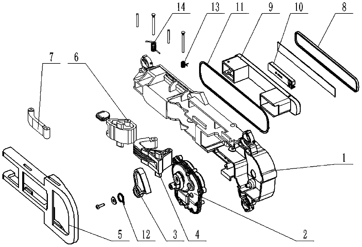
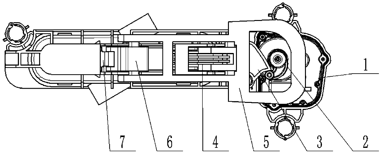
[0032] see Figure 1 to Figure 5 , in one embodiment, a concealed handle for a car door, comprising: a base 1, a motor actuator 2, a first cam 3, a crank arm 4, a drive plate 5, a second cam 6, a drive arm 7, a handle, sensor 10. Wherein, the base 1 is arranged on the inner wall of the vehicle door. The second side of the base 1 is provided with a handle accommodating cavity, and the handle is arranged in the handle accommodating cavity. The door is provided with a slot for accommodating the handle, the first side of the handle is pierced with the slot, and the first side of the handle is flush with the outer wall of the door. The motor actuator 2 is arranged on the first side of the base 1, and an output rod is arranged on the output end of the motor actuator. The first cam 3 is rotatably connected to the base 1, and the first end of the first cam 3 is in contact with the output rod. The curved arm 4 is rotatably connected to the first side of the base 1, and the first en...

Embodiment 2

[0042] a car door, see Figure 1 to Figure 5 , including the concealed handle for a car door in any one of the above-mentioned embodiment one. The base 1 is arranged inside the car door, the motor actuator 2, the first cam 3, the crank arm 4, the driving plate 5, the second cam 6, and the driving arm 7 are all arranged on the first side of the base 1, and the handle One end is set on the second side of the base 1 and is flush with the door shell, and the other end of the handle is pierced through the base 1 and connected to the crank arm 4 and the driving arm 7 respectively; the sensor 10 receives external signals and sends them to the motor actuator control signal, the motor actuator 2 drives the first cam 3 to rotate to a specified position; the first cam 3 drives the connected crank arm 4 to rotate around the point connected to the base 1, so that the crank arm 4 moves, and the crank arm 4's first The two ends push out the first end of the handle; the first end of the cran...


PUM


Abstract

The invention discloses a hidden handle for a vehicle door and the vehicle door. A base is arranged on the inner wall of the vehicle door. A handle containing cavity is arranged in the base, and the handle is arranged in the handle containing cavity. A slot hole for containing the handle is formed in the vehicle door, the first side of the handle is provided with a slot hole in a penetrating manner, and the first side face of the handle is flush with the outer wall of the vehicle door. A motor actuator is arranged on the base, and an output rod is arranged at the output end of the motor actuator. A first cam is rotatably connected to the base, and the first cam is connected to the output rod. A crank arm is rotatably connected to the base, and the crank arm and a driving plate are connected in a clamped manner, one end of the crank arm is connected to the first end, penetrating through the base, of the handle through a pin shaft, and the other end of the crank arm is also connected with the first cam. The driving plate is arranged on the base in a sleeve manner. A second cam is connected to the base through a pin shaft, the second cam and the driving plate are connected in a clamped manner, and the second cam is connected to a drive arm through a pin shaft. The second end of the drive arm is connected to the second end, penetrating through the base, of the handle. A sensor is located in the handle and used for receiving an external signal and transmitting the signal to the motor actuator.

Description

technical field [0001] The invention belongs to the technical field of auto parts, in particular to a hidden handle for a car door and a car door. Background technique [0002] The door is to provide the passage for the driver and passengers to enter and exit the vehicle, and to isolate the interference from the outside of the vehicle, to reduce side impact to a certain extent, and to protect the occupants. The beauty of the car is also related to the shape of the door. The quality of the door is mainly reflected in the anti-collision performance of the door, the sealing performance of the door, the convenience of opening and closing the door, and of course other indicators of use functions. Anti-collision performance is particularly important, because when a vehicle collides sideways, the buffer distance is very short, and it is easy to injure the occupants of the vehicle. [0003] However, the existing car doors only consider the protection function of the people inside ...

Claims


Application Information

Patent Timeline
Patent Type & Authority Applications(China)
IPC IPC(8): E05B85/10
CPCE05B85/107
Inventor 杨锦夫徐晓亮王志顺
Owner GUANGDONG MAIGENA AUTOMOBILE MIRROR IMAGE CO LTD
Learn More