A detachable tooling system and building wall for laminated shear walls

A technique of superimposing shear walls and dismantling tooling, which is applied in construction, building components, building structures, etc., can solve the problems of destroying the integrity and mechanical performance of wall panels, so as to ensure accuracy, save costs, and speed up construction progress effect

Active Publication Date: 2020-06-09
SHANDONG UNIV
View PDF9 Cites 0 Cited by
  • Summary
  • Abstract
  • Description
  • Claims
  • Application Information

AI Technical Summary

Problems solved by technology

[0003] At present, for laminated shear walls, the prefabricated wall panels have reserved holes for positioning tooling. The inventors found that this requires reserving holes through the walls on the prefabricated wall panels, which to a certain extent destroys the integrity and mechanical performance of the wall panels.

Method used


Image

  • A detachable tooling system and building wall for laminated shear walls
  • A detachable tooling system and building wall for laminated shear walls
  • A detachable tooling system and building wall for laminated shear walls

Examples


Embodiment 1

[0061] Attached below figure 1 - attached Figure 16 Further description will be made on the detachable tooling system disclosed in this embodiment;

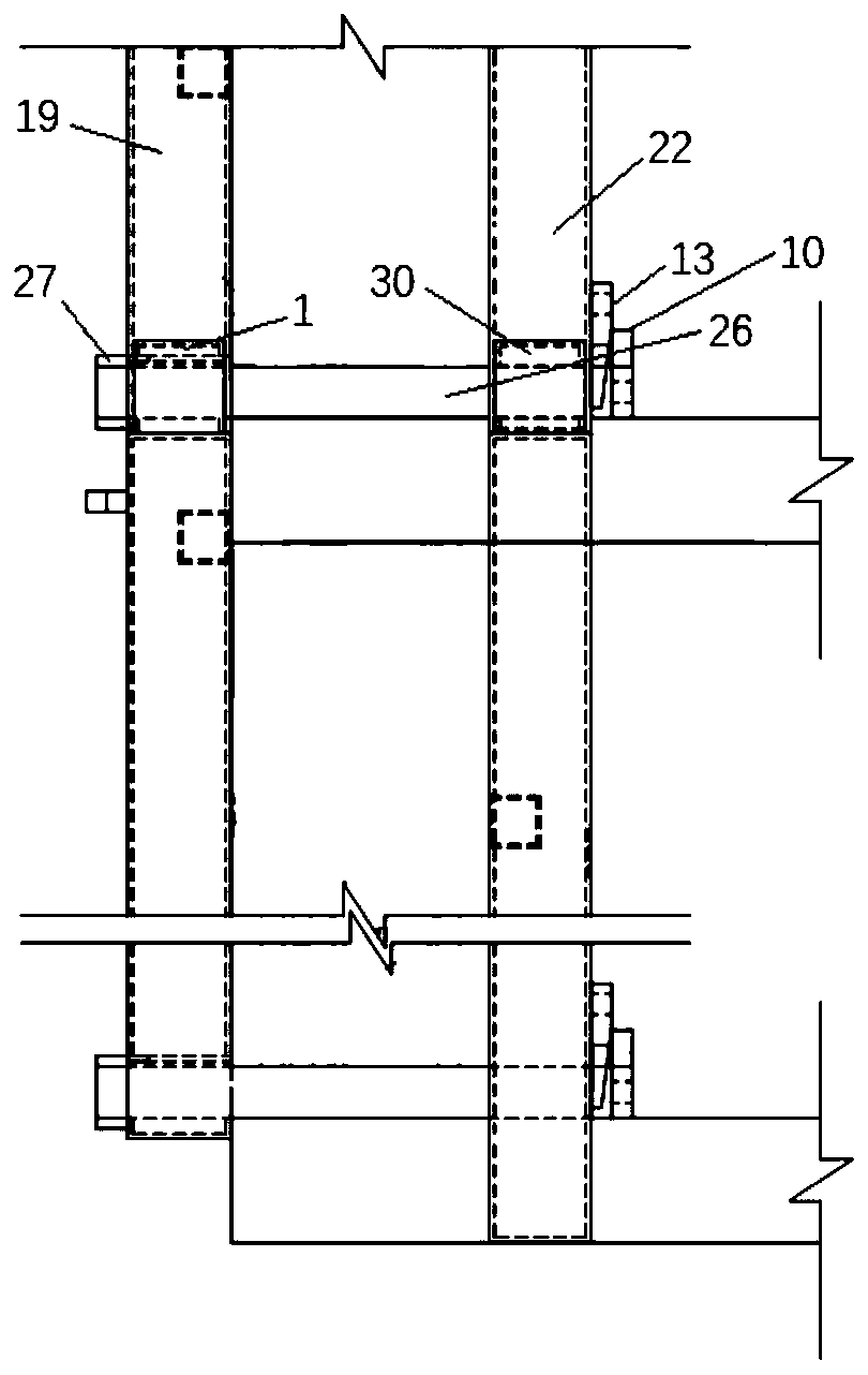
[0062] Refer to attached figure 1 As shown, the detachable tooling system for laminated shear walls includes multi-section inner steel frame units 22 connected up and down in sequence, multi-section outer steel frame units 19 connected up and down in sequence, inserts 26, and inner steel frame units 22 1. The outer steel frame units 19 are arranged side by side, and the plug-in 26 connects the steel frame units 22 in adjacent sections, the steel frame units 19 outside the adjacent sections, and connects the steel frame units 22 and 19 in the same section;

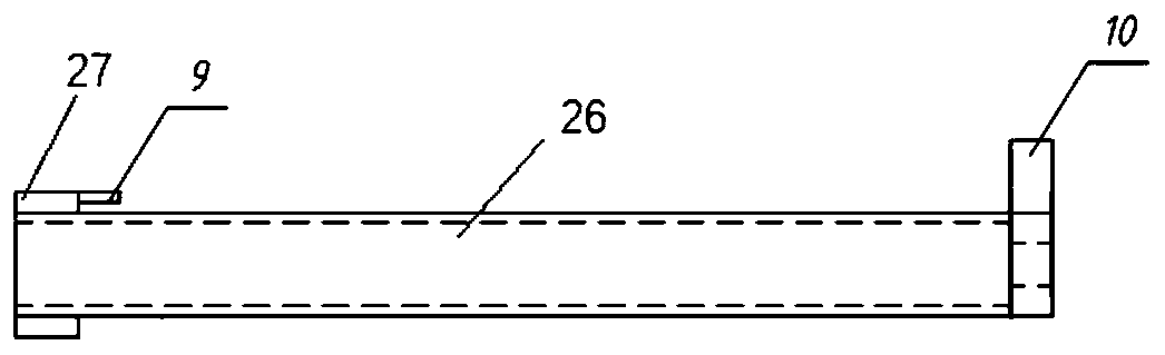
[0063] The first inter-column connecting plate 1 and the second inter-column connecting plate 30 are pierced on the plug-in 26 at intervals; The bottom is fixedly connected to the inner steel frame unit 22;

[0064] Such as figure 2 As shown, the first end of the throug...


PUM


Abstract

The invention discloses a detachable tooling system for a superimposed shear wall and a building wall. The detachable tooling system includes a plurality of sections of inner steel frame units which are successively connected up and down, a plurality of sections of outer steel frame units which are successively connected up and down and penetrating parts, the inner steel frame units and the outer steel frame units are arranged side by side, the adjacent sections of inner steel frame units and the adjacent sections of outer steel frame units are connected through the penetrating parts, and the same section of inner steel frame units and the same section of outer steel frame units are connected through the penetrating parts; first inter-column connecting plates and second inter-column connecting plates are arranged on the penetrating parts in a penetrating mode, the first inter-column connecting plates are fixedly connected with the outer steel frame units, and the second inter-column connecting plates are fixedly connected with the inner steel frame units; limiting plates transversely arranged are fixedly arranged on the first ends of the penetrating parts, and positioning plates vertically arranged are fixedly arranged on the second ends of the penetrating parts; the first inter-column connecting plates are transversely provided with first through holes and limiting holes, and the second inter-column connecting plates are transversely provided with second through holes; and the penetrating parts penetrate through first through holes of the first inter-column connecting plates and second through holes of the second inter-column connecting plates, and the limiting plates are arranged in the limiting holes in a penetrating mode.

Description

technical field [0001] The present disclosure relates to the construction field, in particular to a detachable tooling system for a laminated shear wall and a building wall. Background technique [0002] As a new structural system, laminated shear walls combine the advantages of fast construction progress of prefabricated structures and good integrity of cast-in-place structures, and are playing an increasingly important role in the construction field. The laminated shear wall is mainly composed of three parts in the thickness direction. The inner and outer two-leaf concrete wall panels are prefabricated and connected by truss steel bars. After being installed and fixed on site, the middle cavity is post-cast to form a solid wall that bears overall force. Existing thermal insulation exterior walls of laminated shear walls mostly replace the formwork of the cast-in-place part with inner and outer leaf prefabricated wall panels, but due to the existence of the insulation core ...

Claims


Application Information

Patent Timeline
Patent Type & Authority Patents(China)
IPC IPC(8): E04B2/56E04G11/06E04G17/00
CPCE04B2/56E04G11/06E04G17/001
Inventor 侯和涛巩兆辉武轩宇曹运昌
Owner SHANDONG UNIV
Why Eureka
Try Eureka