A processing method for removing burrs from a solid cage
A solid cage and processing method technology, which is applied in the field of processing to remove burrs from solid cages, can solve problems such as difficult removal of burrs, and achieve the effects of stable processing quality, reduced processing costs, and reduced processing difficulty
- Summary
- Abstract
- Description
- Claims
- Application Information
AI Technical Summary
Problems solved by technology
Method used
Image

Examples
specific Embodiment approach 1
[0060] Embodiment 1: A processing method for removing burrs from a solid cage described in this embodiment, the implementation steps of the method are as follows:
[0061] Step 1: turning and forming;
[0062] Case 1: For steel parts, the forming steps include rough turning, quenching and tempering, and fine turning. The specific operation process is as follows:
[0063] a): Carry out chamfering on the inner diameter of the rough turning and the first end face of the blank; and leave 1.1-1.3mm for the inner diameter of the fine turning, and 0.3-0.5mm for the first end face of the rough turning;
[0064] b): Carry out chamfering on the outer diameter of rough turning and the second end face of the blank; and leave 1.1-1.3mm for the outer diameter of fine turning, and 0.3-0.5mm for the second end face of fine turning;
[0065] c): quenched and tempered rough car parts;
[0066] d): Carry out fine turning inner diameter and first end face chamfering on the quenched and tempered...
specific Embodiment approach 2
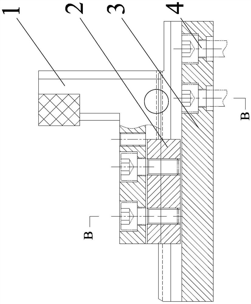
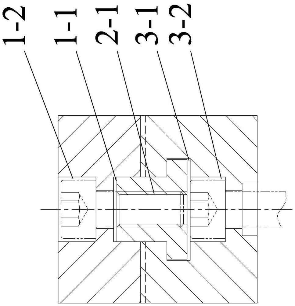
[0100] Embodiment 2: This embodiment is to further limit the processing method for removing burrs from the solid cage described in Embodiment 1. Figure 1 to Figure 4 Describe this embodiment. In this embodiment, the inner diameter positioning tool assembly mentioned in step 8 includes N inner diameter positioning tools, N is a positive integer, and each inner diameter positioning tool includes an inner diameter movable jaw 1, a No. 1 T-shaped Guide key 2, a No. 1 base 3 and four No. 1 bolts 4, the bottom of each inner diameter movable jaw 1 is provided with a No. 1 through slot 1-1 along the length direction, and the top of each No. 1 base 3 is along the length direction There is a No. 1 T-shaped guide groove 3-1, each No. 1 T-shaped guide key 2 is set in a No. 1 T-shaped guide slot 3-1 and a through groove 1-1, and each No. 1 T-shaped The guide key 2 is slidingly connected with a No. 1 T-shaped guide groove 3-1, and one end of each No. 1 T-shaped guide groove 3-1 bottom surf...
specific Embodiment approach 3
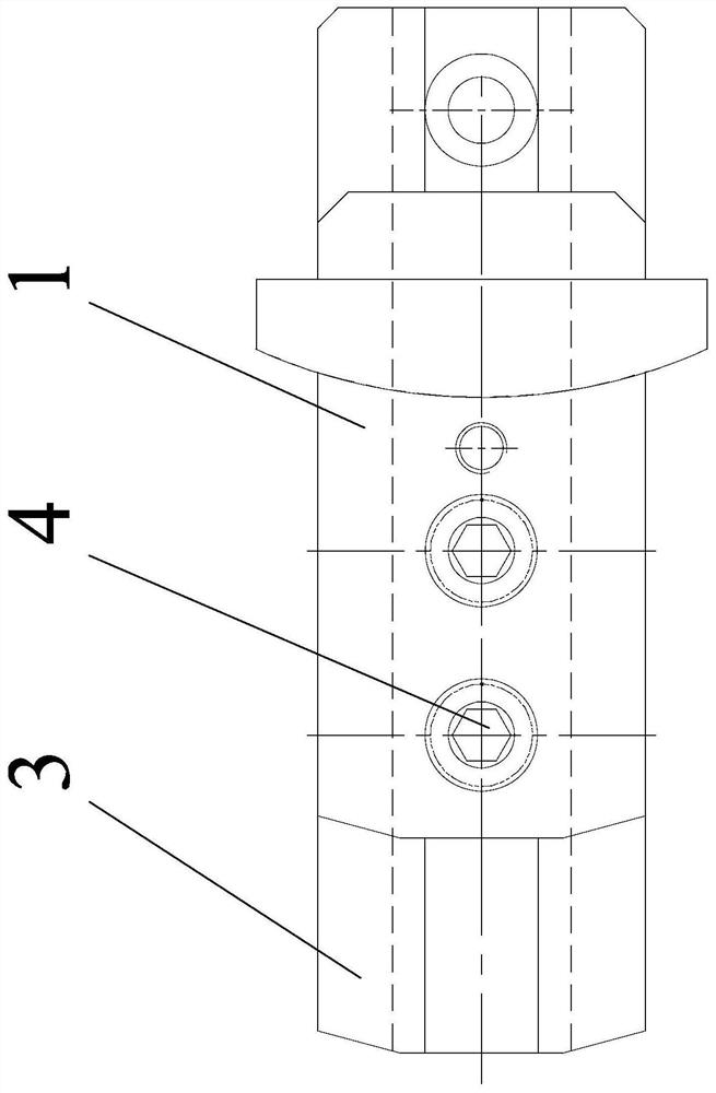
[0101] Embodiment 3: This embodiment is to further limit the processing method for removing burrs from the solid cage described in Embodiment 1. Figure 5 to Figure 8 Describe this embodiment. In this embodiment, the outer diameter positioning tool assembly mentioned in step 8 includes N outer diameter positioning tools, N is a positive integer, and each outer diameter positioning tool includes an outer diameter movable jaw 5, a No. 2 T-shaped guide key 6, a No. 2 base 7 and four No. 2 bolts 8, the bottom of each outer diameter movable jaw 5 is provided with a No. 2 through groove 5-1 along the length direction, and each No. 2 base 7 The top is provided with a No. 2 T-shaped guide groove 7-1 along the length direction, and each No. 2 T-shaped guide key 6 is arranged in a No. 2 T-shaped guide groove 7-1 and two through grooves 5-1, and Each No. 2 T-shaped guide key 6 is slidingly connected with a No. 2 T-shaped guide groove 7-1, and one end of each No. 2 T-shaped guide groove 7...
PUM
 Abstract
Description
Claims
Application Information
 - Generate Ideas
- Intellectual Property
- Life Sciences
- Materials
- Tech Scout
- Unparalleled Data Quality
- Higher Quality Content
- 60% Fewer Hallucinations
Browse by: Latest US Patents, China's latest patents, Technical Efficacy Thesaurus, Application Domain, Technology Topic, Popular Technical Reports.
© 2025 PatSnap. All rights reserved.Legal|Privacy policy|Modern Slavery Act Transparency Statement|Sitemap|About US| Contact US: help@patsnap.com