Snap-type unwound insulator for dense busway conductor

A busway, intensive technology, applied in the field of snap-on non-twisting insulators, can solve the problems of unguaranteed product quality uniformity and reliability, unsatisfactory product quality uniformity, affecting the service life of busbars, etc., so as to reduce the difficulty of production. , The effect of reliable electrical performance of insulation and no hidden quality problems

Pending Publication Date: 2019-10-29
陕西正泰母线科技有限公司
View PDF0 Cites 0 Cited by
  • Summary
  • Abstract
  • Description
  • Claims
  • Application Information

AI Technical Summary

Problems solved by technology

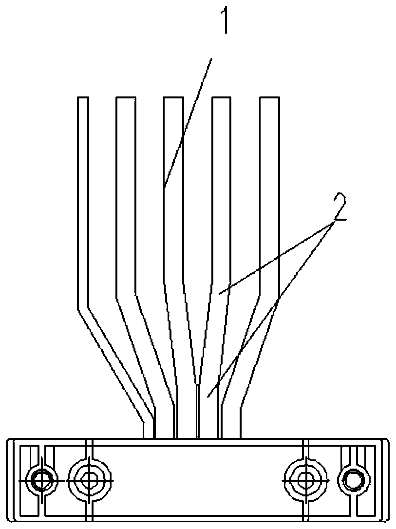
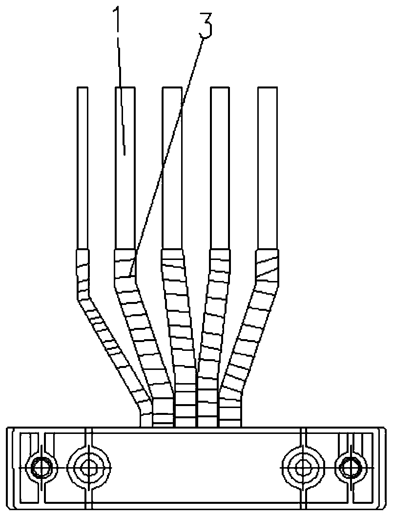
However, due to the influence of manual wrapping and the bending process of the conductive terminal, three layers of 3M tape must be wrapped at the bending part 2 of the terminal, and the winding position of the 3M tape must coincide with the polyester sleeve that wraps the copper bar. Meet the electrical needs of dense busbars
It can be seen that under the wrapping insulator method of dense busway in the prior art, the insulation wrapping and winding of the end of the conductive component of dense busway is difficult and demanding, and the product quality uniformity is not ideal; Influence, when wrapping the conductor bending arc, usually there will be uneven winding, flow wrapping, obvious wrinkles, uneven thickness, especially the defects of air bubbles; therefore, the dense busway made by the traditional wrapping process, the production The efficiency is low, the wrapping technology is difficult, and the work efficiency is low; especially the appearance quality of the product is poor, and the reliability of the product quality uniformity cannot be guaranteed; not only that, but the wrapped dense busway insulator is very difficult during transportation and installation. It may be caused by the friction of assembly or transportation on the wrapped insulator, which will affect the service life of the busway; therefore, the following technical solutions are proposed

Method used


Image

  • Snap-type unwound insulator for dense busway conductor
  • Snap-type unwound insulator for dense busway conductor
  • Snap-type unwound insulator for dense busway conductor

Examples


Embodiment Construction

[0028] Attached below Figure 3-13 Specific examples of the present invention are described.

[0029] The following examples facilitate a better understanding of the present invention, but do not limit the present invention. The materials and components in the following examples are conventional components and materials, unless otherwise specified, and are commercially available.

[0030] In the present invention, unless stated otherwise, it should be understood that the terms "center", "upper", "lower", "front", "rear", "left", "right", "vertical The orientations or positional relationships indicated by "straight", "horizontal", "top", "bottom", "inner" and "outer" are based on the orientations or positional relationships shown in the drawings, and are only for the convenience of describing the present invention and simplifying the Describes, but does not indicate or imply that the device or element referred to must have a specific orientation, be constructed in a specific ...


PUM


Abstract

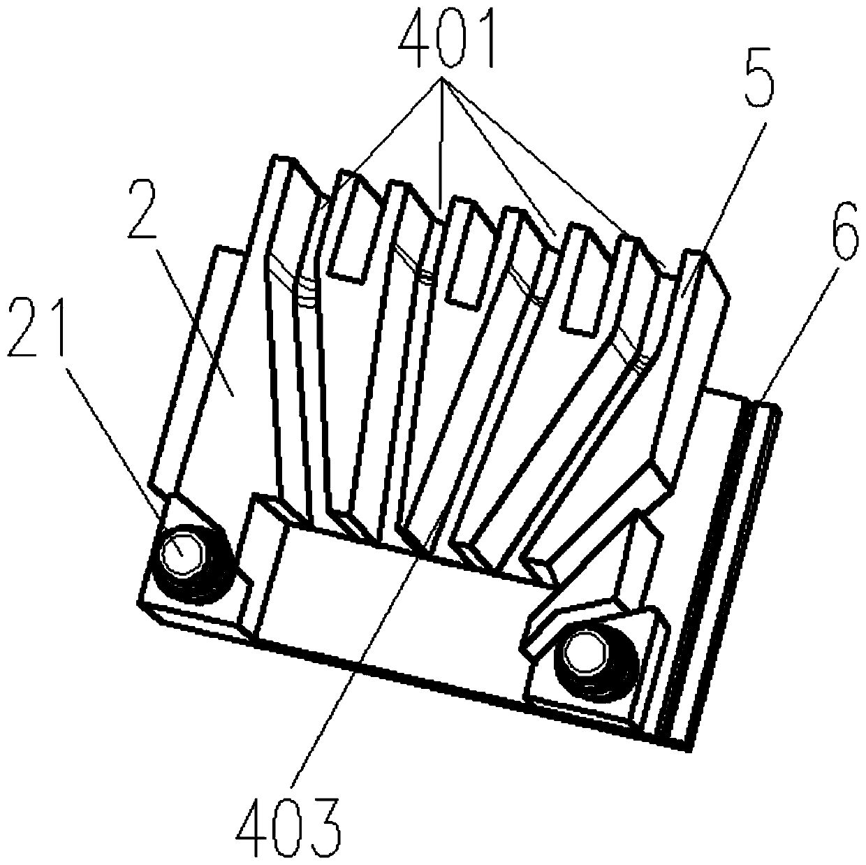
The invention provides a snap-type unwound insulator for a dense busway conductor. The insulator comprises an insulating body composed of an upper sheath and a lower sheath. The outer sides of the upper and lower sheaths are fixedly connected into a whole body through matched clamp joint of a convex clamp block and a concave clamp slot. An upper row of U-shaped clamp slots and a lower row of U-shaped clamp slots, which correspondingly match the copper bars of the phases of a bus are arranged on the inner sides of the upper and lower sheath bodies. The buckled upper and lower sheaths are provided with a number of insulation channels correspondingly matching the copper bars of the phases of the bus. A number of insulation channels limit, fix, clamp and package the bottom insulation parts ofthe copper bars of the phases of the bus in the insulating body. The insulation channel fittings are closely attached to each other to form a whole body by using a close-fitting child-mother structure. According to the invention, the process difficulty of manufacturing the insulating part of the conductor is reduced; the product quality and the work efficiency are improved; the production cost iscontrolled; and the insulator has the advantages of uniform insulating sheath type, high degree of standardization, reliable quality, being wear-resisting and durable and excellent electrical performance.

Description

technical field [0001] The invention belongs to the technical field of dense bus ducts for electrical power transmission and distribution, and in particular relates to a snap-fit ​​non-winding insulator used for conductors of dense bus ducts. Background technique [0002] With the emergence of modern engineering facilities and equipment, the power consumption of all walks of life is increasing rapidly. During the construction and wiring installation of high-rise buildings and large-scale workshops, cables for power transmission are required to meet the parallel use of multiple cables and reduce the number of multiple cables. On-site installation, construction, connection and wiring of cables are difficult, and dense bus ducts for low-voltage integrated power supply to transmit and distribute electric energy have emerged as the times require. Under the existing technology, (such as figure 1 As shown) the dense busway is mainly composed of three parts: the bottom shell, the c...

Claims


Application Information

Patent Timeline
Patent Type & Authority Applications(China)
IPC IPC(8): H02G5/06H01B17/60H01B17/66
CPCH02G5/066H01B17/60H01B17/66
Inventor 周林海肖光辉高孝科谷少敏任琨
Owner 陕西正泰母线科技有限公司
Why Eureka
Try Eureka