Drilling machine for workpiece milling

A milling and drilling technology, applied in the direction of metal processing machinery parts, milling cutters, manufacturing tools, etc., can solve the problems of poor chamfering effect, low efficiency of nylon shaft milling slots, adjustment, etc., and achieve the effect of increasing slotting accuracy

Active Publication Date: 2021-06-11
海盐瑞扬新材料股份有限公司
View PDF12 Cites 0 Cited by
  • Summary
  • Abstract
  • Description
  • Claims
  • Application Information

AI Technical Summary

Problems solved by technology

[0004] 1. After the slot milling of the nylon shaft, it is necessary to chamfer the slot opened. This step needs to be carried out in two steps, which makes the milling efficiency of the nylon shaft low. At the same time, the chamfering effect of the nylon shaft opening slot alone is poor;
[0005] 2. The milling depth of the nylon shaft cannot be limited when the slot is milled, and the cutting fluid sprayed during the slot milling of the nylon shaft cannot be adjusted for the spray angle

Method used


Image

  • Drilling machine for workpiece milling
  • Drilling machine for workpiece milling
  • Drilling machine for workpiece milling

Examples


Embodiment Construction

[0026] In order to make the technical means, creative features, goals and effects achieved by the present invention easy to understand, the present invention will be further described below in conjunction with specific illustrations. It should be noted that, in the case of no conflict, the embodiments in the present application and the features in the embodiments can be combined with each other.

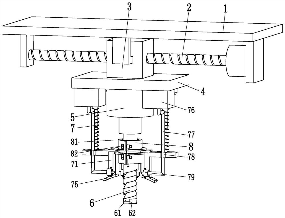
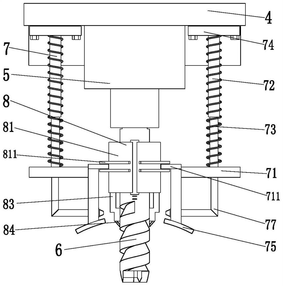
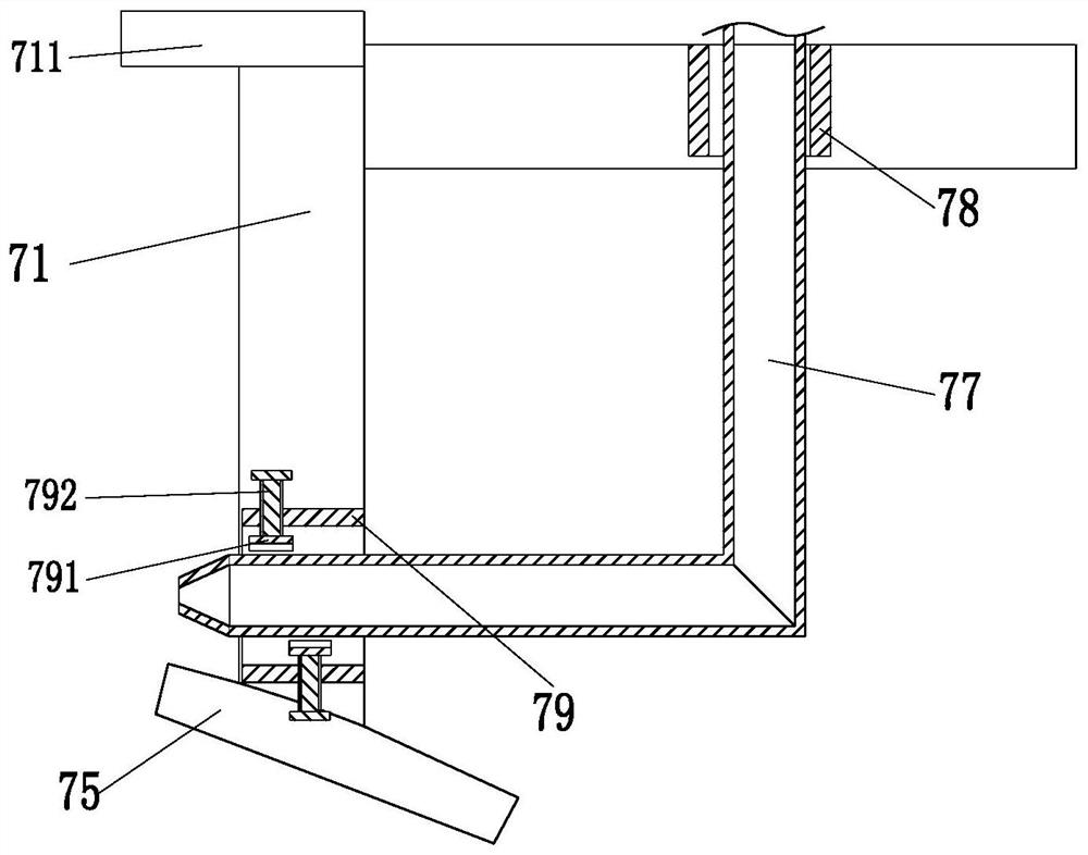
[0027] Such as Figure 1 to Figure 3 As shown, a drilling machine for workpiece milling includes a top plate 1, a moving screw 2, a moving slider 3, a hanging plate 4, a rotating motor 5, a milling cutter 6 and a limit mechanism 7, and the bottom of the top plate 1 A moving screw 2 is installed on the top, and a moving slider 3 is installed on the middle part of the moving screw 2. The outer end of the moving slider 3 is provided with a sliding rod, and the upper end of the sliding rod on the moving slider 3 is fitted with the top plate The bottom of 1 is connected, the hanging plat...


PUM


Abstract

The invention relates to a drilling machine for workpiece milling, which includes a top plate, a moving screw, a moving slider, a hanging plate, a rotating motor, a milling cutter and a limit mechanism. The slider is installed on the middle of the moving screw, and the outer end of the moving slider is provided with a sliding rod. The upper end of the sliding rod on the moving slider is connected with the bottom of the top plate through a sliding fit. On the bottom, the rotating motor is installed on the lower end surface of the middle part of the hanging plate through the motor sleeve, and a milling cutter is installed on the rotating motor, and a limit mechanism is distributed on the left and right ends of the rotating motor, and the limit mechanism is installed on the bottom of the hanging plate . The present invention can solve the problem that the existing nylon shaft needs to be chamfered after the slot milling of the nylon shaft is completed, so that the slot milling efficiency of the nylon shaft is low, and the nylon shaft cannot be milled when the slot is milled. The groove depth is limited and other issues.

Description

technical field [0001] The invention relates to the technical field of cutting processing, in particular to a drilling machine for workpiece milling. Background technique [0002] The slot milling machine cuts various metal materials or synthetic materials into slots through a specific tool. The slot milling machine generally cuts the knife directly to a certain depth on the center line of the slot, and then controls the milling cutter to mill back and forth, so that the processed workpiece is milled. to the specified depth and size. [0003] Due to the large number of applications of nylon parts, nylon materials, especially nylon shafts, need to be milled frequently. Compared with ordinary metal materials, nylon materials have poor heat resistance. A large amount of cutting fluid is sprayed at the position so that the cutting position of the nylon shaft will not be deformed due to overheating. The specific problems existing in the milling of the existing nylon shaft are as...

Claims


Application Information

Patent Timeline
Patent Type & Authority Patents(China)
IPC IPC(8): B23C3/28B23C5/10B23C9/00B23Q11/10B23P23/02
CPCB23C3/28B23C5/10B23C9/00B23C2210/20B23P23/02B23Q11/10
Inventor 张秋龙陶娟王飞翔
Owner 海盐瑞扬新材料股份有限公司
Why Eureka
Try Eureka