
A FRP desulfurization tower using waste heat power to remove slag

A desulfurization tower and FRP technology, applied in lighting and heating equipment, separation methods, reduction of greenhouse gases, etc., can solve the problems of low dust removal efficiency, time-consuming and labor-intensive problems of flue gas, save time and effort in cleaning work, improve dust removal efficiency, and accelerate The effect of dust falling

Active Publication Date: 2021-09-24
桂阳银龙科技有限责任公司
View PDF12 Cites 1 Cited by
  • Summary
  • Abstract
  • Description
  • Claims
  • Application Information

AI Technical Summary

Problems solved by technology

[0003] The glass fiber reinforced plastic desulfurization tower using waste heat power to remove slag in the prior art has the following problems: the settlement heat exchange chamber and the smoke inlet pipe of the existing glass desulfurization tower using waste heat power to remove slag (reference document: CN201520730919.6) are integrated Formed structure, although this structure does not affect the normal work of the sedimentation heat exchange chamber, but it makes the work of cleaning up harmful substances on the inner wall of the smoke inlet tube become time-consuming and laborious, and the dust removal efficiency of the flue gas is low, requiring secondary dust removal

Method used


Image

  • A FRP desulfurization tower using waste heat power to remove slag
  • A FRP desulfurization tower using waste heat power to remove slag
  • A FRP desulfurization tower using waste heat power to remove slag

Examples


Embodiment Construction

[0028] In order to make the technical means, creative features, goals and effects achieved by the present invention easy to understand, the present invention will be further described below in conjunction with specific embodiments.

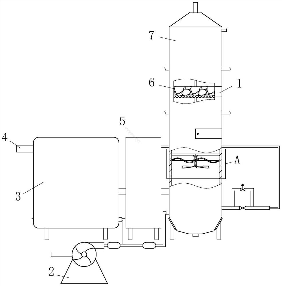
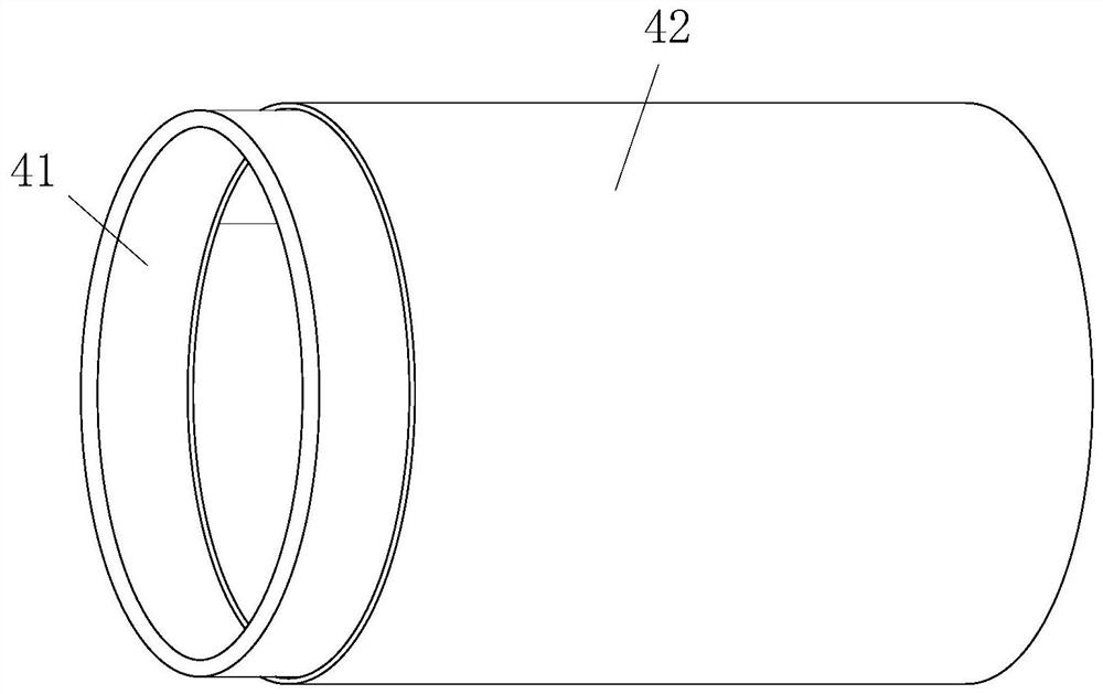
[0029] Such as Figure 1 to Figure 7 As shown, a glass fiber reinforced plastic desulfurization tower using waste heat power to remove slag includes a settling heat exchange chamber 3, one side of the settling heat exchange chamber 3 is provided with a pressurized fan 2, and the other side of the settling heat exchange chamber 3 A cooling water tank 5 is provided at a position of 90 degrees to the pressurized fan 2, and a desulfurization tower main body 7 is provided on the side of the cooling water tank 5 far away from the settling heat exchange chamber 3, which is characterized in that the settling heat exchange chamber 3 is far away from One side of the cooling water tank 5 is provided with a smoke inlet assembly 4, and the smoke inlet assembly...


PUM


Abstract

The invention belongs to the technical field of desulfurization equipment, and specifically relates to a glass fiber reinforced plastic desulfurization tower using waste heat power to remove slag, including a sedimentation heat exchange chamber, a pressurized fan is arranged on one side of the sedimentation heat exchange chamber, and the sedimentation heat exchange chamber On the other side of the chamber and at a position 90 degrees from the pressurized fan, a cooling water tank is provided. The desulfurization tower main body is provided on the side of the cooling water tank away from the sedimentation heat exchange chamber, and the side of the sedimentation heat exchange chamber is away from the cooling water tank. A smoke inlet component is provided. In the present invention, the packing layer and the main body of the desulfurization tower are fixed by connecting components. The connecting component includes a support frame, a connecting port, a connecting hole, a connecting plate and a connecting bolt. When assembling, the packing layer is put into the groove of the connecting plate, and then the The packing layer is pushed into the top of the support frame through the connection port until the connecting bolts of the connecting plate stop connecting with the connecting holes. This structure is easy to disassemble and replace the packing layer regularly, and can treat the dust in the flue gas, improving the treatment efficiency. quality.

Description

technical field [0001] The invention belongs to the technical field of desulfurization equipment, in particular to a glass fiber reinforced plastic desulfurization tower which utilizes waste heat power to remove slag. Background technique [0002] With social development and industrial progress, FRP desulfurization towers are used more and more frequently, among which FRP desulfurization towers using waste heat power to remove slag have the widest application range, although the existing FRP desulfurization towers using waste heat power to remove slag The production process is becoming more and more mature, but there are still some deficiencies that need to be improved. The dust removal efficiency is for dust with a certain range of particle sizes. The efficiency is 50%. [0003] The glass fiber reinforced plastic desulfurization tower using waste heat power to remove slag in the prior art has the following problems: the settling heat exchange chamber and the smoke inlet pi...

Claims


Application Information

Patent Timeline
Patent Type & Authority Patents(China)
IPC IPC(8): B01D46/10B01D46/00B01D45/02B01D50/00F23J15/06B01D53/78B01D53/48
CPCB01D46/10B01D45/02F23J15/06B01D53/78B01D53/48B01D2258/0283B01D46/76B01D50/20Y02E20/30
Inventor 曹剑锋李家元梁之凯刘振闫羽邢建
Owner 桂阳银龙科技有限责任公司
Learn More