Energy-saving and environmentally friendly industrial waste gas treatment device

A technology of industrial waste gas and treatment equipment, which is applied in the direction of gas treatment, combustion type, transportation and packaging, etc., and can solve the problems of incomplete reaction of substances in waste gas, cumbersome engineering, accumulation, etc.

Inactive Publication Date: 2019-09-20
莫庆锋
View PDF10 Cites 2 Cited by
  • Summary
  • Abstract
  • Description
  • Claims
  • Application Information

AI Technical Summary

Problems solved by technology

[0003] The existing industrial waste gas treatment device provided by CN 105194962 A can cool and purify the waste gas by setting an absorption tower, which ensures the cleanliness of the industrial working environment and avoids pollution to the environment. However, when the purification liquid is replaced, the engineering cumbersome
[0004] The existing CN 107551793 A provides an industrial waste gas treatment device, which pre-combusts the combustible waste gas in the industrial waste gas, and then absorbs and filters the activated carbon adsorption plate in the gas filter device, and some unabsorbed waste gas is passed through The air outlet hole on the air pipe enters the bottom of the box and reacts with the alkaline reaction liquid, but the particles in the exhaust gas cannot be processed and will accumulate at the inlet
[0005] An industrial waste gas treatment device provided by the existing CN 107019976 A can use a liquid medicine tank to spray acidic or alkaline liquid medicine into the waste gas treatment box, thereby removing acidic or alkaline harmful substances in industrial waste gas, but the method of spraying liquid medicine It will make the substances in the exhaust gas not react completely

Method used


Image

  • Energy-saving and environmentally friendly industrial waste gas treatment device
  • Energy-saving and environmentally friendly industrial waste gas treatment device
  • Energy-saving and environmentally friendly industrial waste gas treatment device

Examples


Embodiment Construction

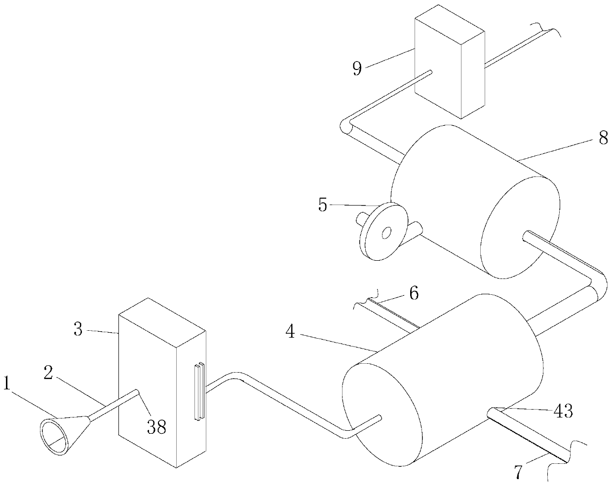
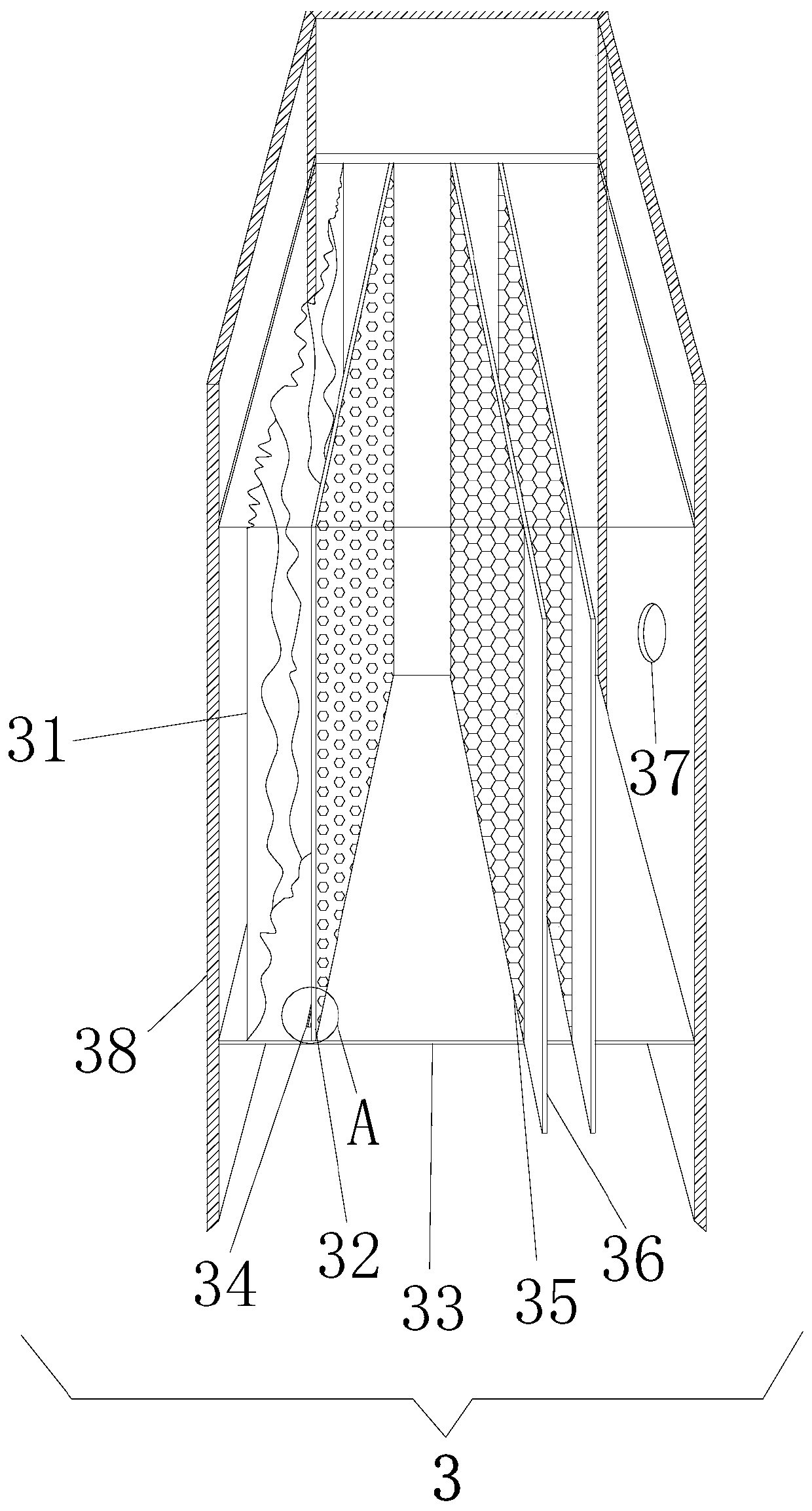
[0031] Such as Figure 1-5 As shown, the present invention provides a technical solution: an energy-saving and environment-friendly industrial waste gas treatment device, including a waste gas collection device 1, the waste gas collection device 1 is a hollow conical shape with a large front and a small rear, and the small mouth end of the waste gas collection device 1 passes through the pipe 2 The filter air inlet 38 on the filter box 39 is fixedly connected, and the filter air inlet 38 is provided with a filter air outlet 37 on the opposite side of the filter box 39, and the filter air inlet 38 and the filter air outlet 37 are in the filter box 39 The positions are relatively symmetrical, the pipeline 2 is an ordinary connecting pipeline, and the filter box 39 is a composition of the filter device 3. The filter box 39 is a hollow cuboid, and the inside of the filter box 39 is fixedly equipped with two fixed plates 33, and the fixed plate 33 four sides are all fixed on the fi...


PUM


Abstract

The invention provides an energy-saving and environmentally friendly industrial waste gas treatment device, and relates to the technical field of industrial waste gas treatment. The energy-saving and environmentally friendly industrial waste gas treatment device includes a waste gas collection device. The waste gas collection device is fixedly connected to a filter device through a pipeline. Fixed plates are fixedly mounted in the filter device. Wet filter paper, a gas permeable plate and activated carbon plates are fixedly connected between the two fixed plates. Leakage grooves are arranged between each wet filter paper and the corresponding gas permeable plate. The two activated carbon plates are fixedly mounted behind the corresponding gas permeable plate. An extension plate is fixedly mounted on the right side of the corresponding activated carbon plates. The filter device is fixedly connected to a purification device through a pipeline. A flow guiding pipe is fixedly mounted in the purification device. A catalytic combustion device is fixedly mounted behind he purification device. A drying device is fixedly connected behind the catalytic combustion device. The filter device makes solid waste such as particles in the waste gas be first intercepted by the wet filter paper, and the solid waste can be intercepted by the gas permeable plates if the solid waste passes through the wet filter paper and falls into the leakage grooves, which does not affect the operation of the whole device.

Description

technical field [0001] The invention relates to the technical field of industrial waste gas, in particular to an energy-saving and environment-friendly industrial waste gas treatment device. Background technique [0002] Industrial waste gas refers to the general term for all kinds of pollutant gases that are discharged into the air during fuel combustion and production processes in the factory area. Now many factories produce a large amount of waste gas. Waste gas treatment will also be carried out. [0003] The existing industrial waste gas treatment device provided by CN 105194962 A can cool and purify the waste gas by setting an absorption tower, which ensures the cleanness of the industrial working environment and avoids pollution to the environment. However, when the purification liquid is replaced, the engineering cumbersome. [0004] The existing CN 107551793 A provides an industrial waste gas treatment device, which pre-combusts the combustible waste gas in the ind...

Claims


Application Information

Patent Timeline
IPC IPC(8): B01D46/00B01D53/04B01D53/78F23G7/07B01D53/26
CPCB01D46/0035B01D46/0036B01D53/0407B01D53/78F23G7/07B01D53/26B01D2253/102B01D2258/02B01D2259/40084B01D46/64Y02A50/20
Inventor 不公告发明人
Owner 莫庆锋
Why Eureka
Try Eureka