A fast air fryer
An air fryer and fan technology, applied in the direction of roaster/barbecue grid, kitchen utensils, household utensils, etc., can solve the problems of low heating efficiency of air fryer, unfavorable fast flow of air flow, air velocity and pressure attenuation, etc., to achieve Improve cooking efficiency, facilitate heating efficiency, and quickly air out the effect
- Summary
- Abstract
- Description
- Claims
- Application Information
AI Technical Summary
Problems solved by technology
Method used
Image

Examples
Embodiment 1
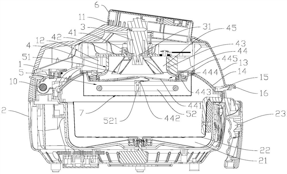
[0037] Such as Figure 1 to Figure 3 As shown, the air fryer of this embodiment includes an upper shell 1 and a lower shell 2, both of which are heat-resistant plastic shells, and the upper shell 1 and the lower shell 2 are connected by a hinge shaft 10 is hinged, so that the upper casing 1 is rotatably arranged above the lower casing 2, the upper casing 1 is provided with an air inlet 11, and the air inlet 11 is located on the top of the upper casing 1, and the upper casing 1 is provided with a motor 3 , the air guide cover 4 and the hot air assembly 5, the lower housing 2 is provided with a cavity 21, and the cavity 21 is provided with a fryer 22, and the fryer 22 is placed in the cavity 21 along the vertical direction, and one part of the fryer 22 There is a fryer handle 23 on the side, and the lower shell 1 is provided with a gap for the fryer handle 23 to accommodate. When the fryer 22 is installed in place, the fryer handle 23 will close the gap, so that the cavity 21 is...
Embodiment 2
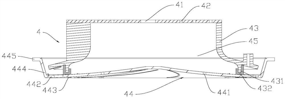
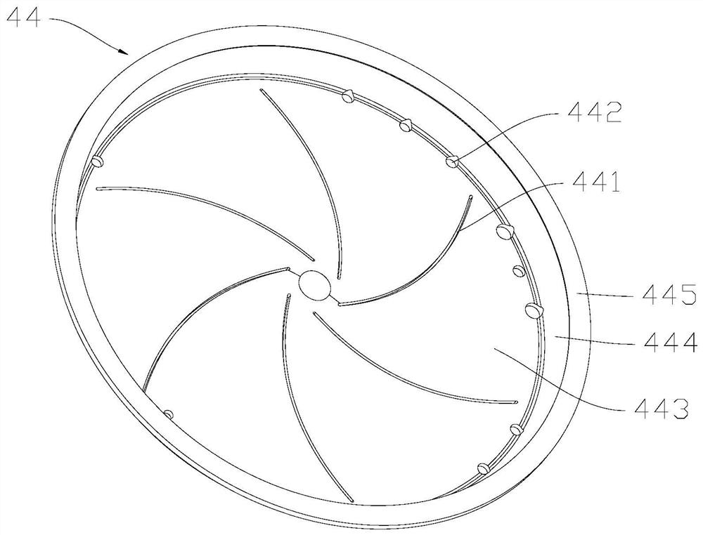
[0051] The difference between this embodiment and Embodiment 1 is that the structure of the bottom cover is different. Figure 4 to Figure 6 As shown, the base plate 443 of the bottom cover 44 in this embodiment is provided with several guide plates 446 that are folded up, and the guide plates 446 are evenly distributed around the center of the base plate 443, and an air outlet gap 441 is formed between the guide plate 446 and the base plate 443. The air outlet slit 441 is formed by the height difference between one side of the guide plate 446 and the base plate 443, so that the airflow formed in the wind gathering chamber 45 is ejected from the air outlet slit 441 in a spiral rotation, because the airflow in the wind gathering chamber 45 is Rotating airflow, this mechanism of side airflow, makes most of the original airflow rotate and shoot out, retaining the original rotation speed of the airflow, and the side airflow ensures that the rotating airflow is a spiral rotation, an...
Embodiment 3
[0055] The difference between this embodiment and Embodiment 1 is that the upper casing and the lower casing are connected differently. As shown in connection 7, the upper casing 1 and the lower casing 2 of this embodiment are fixedly connected, and the upper casing 1 and the lower casing are fixedly connected. The casing 2 is integrally formed to form a cover-shaped casing, the top of the cover-shaped casing is provided with a top cover 8, the bottom of the cover-shaped casing is provided with a bottom cover 9, and the operation panel 6 is located on the front side of the upper casing 1, that is, The upper part of the front side, the front side of the lower shell 2, that is, the lower part of the front side of the cover-shaped housing, is provided with an opening 24, and the fryer 22 can be drawn and installed in the cavity along the opening 24, and the front side of the fryer 22 is provided with a fryer panel 25 , the fryer handle 23 is located on the fryer panel 25. After th...
PUM
 Abstract
Description
Claims
Application Information
 - R&D
- Intellectual Property
- Life Sciences
- Materials
- Tech Scout
- Unparalleled Data Quality
- Higher Quality Content
- 60% Fewer Hallucinations
Browse by: Latest US Patents, China's latest patents, Technical Efficacy Thesaurus, Application Domain, Technology Topic, Popular Technical Reports.
© 2025 PatSnap. All rights reserved.Legal|Privacy policy|Modern Slavery Act Transparency Statement|Sitemap|About US| Contact US: help@patsnap.com