Heating device and heating method inside refractory container

A heating device and heating method technology, which are applied in lighting and heating equipment, casting melt containers, furnace control devices, etc., can solve the problems of difficult to heat refractory container refractories, troublesome control, troublesome and other problems

Active Publication Date: 2020-12-01
CHUGAI RO CO LTD
View PDF6 Cites 0 Cited by
  • Summary
  • Abstract
  • Description
  • Claims
  • Application Information

AI Technical Summary

Problems solved by technology

[0008] However, as shown in the above-mentioned Patent Document 1, there are technical problems such as the following technical problems: while continuously measuring the amount of moisture contained in the refractory material on the inner surface side of the refractory material container, it is difficult to control the amount of combustion gas of the heating burner to perform drying. It is very troublesome, the equipment cost is very high, and it is difficult to quickly heat the refractory on the inner surface side of the refractory container, and in addition, it is difficult to properly control the temperature change of the refractory on the inner surface side of the refractory container
[0010] However, even in the proposal shown in Patent Document 2, there are technical problems such as the following technical problems: in order to dry the refractory construction body by heating it to a predetermined target temperature, the control is very troublesome, and the equipment cost is very high. In addition, if a gap is provided between the refractory construction body and the cover as shown in the above-mentioned Patent Document 1, it is difficult to increase the temperature, and it is difficult to quickly heat the refractory body inside the refractory construction body, and it is also difficult to properly control the temperature. Change of temperature of refractory inside refractory construction body

Method used


Image

  • Heating device and heating method inside refractory container
  • Heating device and heating method inside refractory container
  • Heating device and heating method inside refractory container

Examples


Embodiment Construction

[0031] Hereinafter, a heating device and a heating method inside a refractory container according to an embodiment of the present invention will be specifically described based on the drawings. In addition, the heating device and heating method inside the refractory container of the present invention are not limited to the following embodiments, and can be appropriately changed and implemented within a range that does not change the gist of the invention.

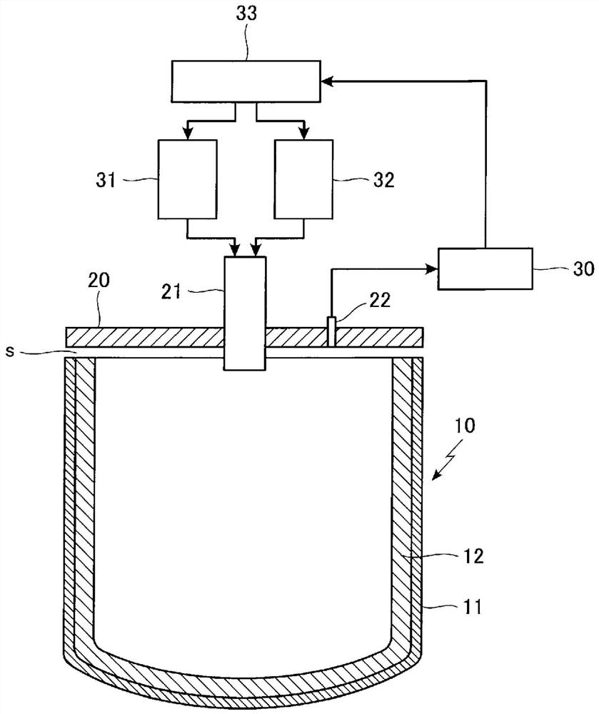
[0032] In the heating device inside the refractory container of this embodiment, if figure 1 , etc., as the refractory container 10, a pot-shaped member with an open upper surface, in which a refractory 12 is provided on the inner surface of an outer wall portion 11 made of steel or the like is used.

[0033] In addition, above the opening portion of the upper surface of the refractory container 10, a cover material 20 is arranged so as to cover it with a gap s (about 10 to 20 cm), and the refractory container is provided in ...


PUM


Abstract

The cover is disposed so as to cover at least the opening of the upper surface of the refractory container made of refractory on the inner surface side through a gap, and when the inside of the refractory container is heated by a burner installed to penetrate the cover, The burner is provided with a continuous combustion control mechanism that adjusts the amount of combustion while continuously burning fuel with the burner, and an on / off combustion control mechanism that adjusts the switching time of burning and stopping of fuel by the burner and the amount of combustion. A switching device for switching combustion of the burner between said continuous combustion control mechanism and said on / off combustion control mechanism.

Description

technical field [0001] The present invention relates to a heating device and a heating method inside a refractory container that is used in a molten metal container, a tundish, etc., and at least the inner surface side is made of a refractory material. In particular, it is characterized in that when heating the inside of the refractory container, the temperature rise inside the refractory container can be appropriately controlled so that the entire interior of the refractory container can be appropriately heated. Background technique [0002] Conventionally, in a refractory container in which at least the inner surface side is made of a refractory material used in a molten metal container, a tundish, etc., the refractory material on the inner surface side is periodically replaced. [0003] And, when the refractory on the inner surface side of the refractory container is replaced as described above, a cover material is provided above the refractory container, and a burner for...

Claims


Application Information

Patent Timeline
Patent Type & Authority Patents(China)
IPC IPC(8): F27D1/16B22D41/01F26B21/00F26B25/00F27D19/00
CPCB22D41/01F26B21/00F26B25/00F27D1/16F27D19/00F27D2019/0034
Inventor 友泽健一河本祐作片山智树丁骁腾
Owner CHUGAI RO CO LTD
Why Eureka
Try Eureka