Innovative design of diopter type safety warning board
An innovative design, warning sign technology, applied in display devices, markings, instruments, etc., can solve problems such as the inability to quickly determine the distance of warning signs
- Summary
- Abstract
- Description
- Claims
- Application Information
AI Technical Summary
Problems solved by technology
Method used
Image

Examples
Embodiment 1
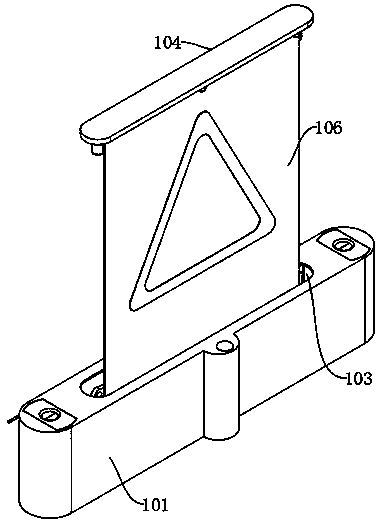
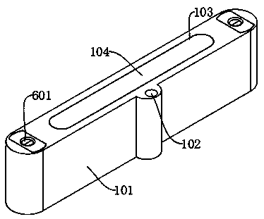
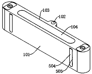
[0030] The innovative design of the anvil-hole type safety warning sign includes: a mobile protective shell 101, an anvil hole 102 and a limiting groove 103. An anvil hole 102 is arranged on the front inner side of the movable protective shell 101, and a limiting groove 103 is arranged on the upper middle part of the mobile protective shell 101. The limit slot 103 internal movable socket is provided with a fixed mount 104 on the warning board, the lower end of the upper fixed mount 104 on the warning board is fixedly connected with the upper end of the warning board deployment mechanism, and the lower end of the display board deployment mechanism is fixedly connected with the upper surface of the lower fixed mount 105 of the warning board. The outer edge of the fixed frame 105 under the sign is fixedly connected with the inner wall of the mobile protection shell 101, the lower end of the fixed frame 105 of the warning sign is fixedly connected with the recovery mechanism of the ...
Embodiment 2
[0032] Embodiment 2: the difference based on Embodiment 1 is;
[0033] The driving mechanism includes: servo motor 201, ratchet 202, rotating screw mandrel 203, rotating gear 204, driving screw mandrel 205, rotating helical gear 206, driving helical gear 207 and transmission shaft 208, and the left and right sides of the mobile protection shell 101 are fixedly installed with Servo motor 201, the main shaft of servo motor 201 is fixedly connected with the axis center of ratchet 202, the upper end of the main shaft of servo motor 201 is fixedly connected with the lower end of rotating screw mandrel 203, the upper end of rotating screw mandrel 203 is movably connected with the inner wall of mobile protection shell 101, the outer side of ratchet wheel 202 is connected with the rotating gear The inside of 204 is meshed and connected, the axis of the rotating gear 204 is fixedly connected to the middle of the transmission screw 205, the upper and lower ends of the transmission screw ...
Embodiment 3
[0036] Embodiment 3: the difference based on embodiment 1 and 2 is;
[0037] Warning sign unfolding mechanism comprises: rotating support rod 301, transmission support rod 302, support rotating shaft 303 and driving wheel group 304, and rotating shaft 208 rear end is fixedly connected with driving wheel group 304 outer ends, and driving wheel group 304 inner end shaft centers The front end of the supporting rotating shaft 304 is fixedly connected, the middle part of the supporting rotating shaft 304 is fixedly socketed inside the lower end of the rotating support rod 301, the front end of the supporting rotating shaft 304 is movably socketed inside the lower fixing frame 105 of the warning sign, and the upper end of the supporting rotating shaft 304 passes through the rotating shaft and the transmission. The lower end of the support rod 302 is movably connected, and the upper end of the transmission support rod 302 is movably connected with the upper fixing frame 104 of the war...
PUM
 Abstract
Description
Claims
Application Information
 - R&D
- Intellectual Property
- Life Sciences
- Materials
- Tech Scout
- Unparalleled Data Quality
- Higher Quality Content
- 60% Fewer Hallucinations
Browse by: Latest US Patents, China's latest patents, Technical Efficacy Thesaurus, Application Domain, Technology Topic, Popular Technical Reports.
© 2025 PatSnap. All rights reserved.Legal|Privacy policy|Modern Slavery Act Transparency Statement|Sitemap|About US| Contact US: help@patsnap.com