Narrow tape gluing device and full-automatic mirror cabinet edge gluing machine based on same

A gluing device and gluing mechanism technology, applied in the direction of transportation and packaging, winding strips, sending objects, etc., can solve the problems of reducing the efficiency of gluing, wrinkles of the adhesive layer, and low winding tension, so as to improve the gluing The effect of glue quality, reducing wrinkles, and small tension deviation range

Pending Publication Date: 2019-09-17
中山科勒卫浴有限公司
View PDF0 Cites 3 Cited by
  • Summary
  • Abstract
  • Description
  • Claims
  • Application Information

AI Technical Summary

Problems solved by technology

Adhesive tapes are generally applied by a gluing machine. Since the ordinary gluing machine uses a motor to control the unwinding and rewinding of the tape, it is generally suitable for wide tapes (>1cm), and the tape used for gluing the edge of the mirror cabinet. The width is narrow, and the rewinding tension it can withstand is much lower than that of wide tape; in addition, during the unwinding process, as the radius of the tape shrinks and the radius of the rewinding material increases, the rewinding tension will become larger and larger, and the release The paper is prone to breakage during the winding process, resulting in the forced stop of the gluing equipment, which greatly reduces the gluing efficiency
In addition, due to the deviation of the winding tension of the tape itself during the production and winding process, the tightness of the finished tape is inconsistent. Using an ordinary gluing machine, the adhesive layer is prone to wrinkles due to the unstable tension during gluing, which seriously affects Adhesive quality

Method used


Image

  • Narrow tape gluing device and full-automatic mirror cabinet edge gluing machine based on same
  • Narrow tape gluing device and full-automatic mirror cabinet edge gluing machine based on same
  • Narrow tape gluing device and full-automatic mirror cabinet edge gluing machine based on same

Examples


Embodiment Construction

[0033] In order to deepen the understanding of the present invention, the present invention will be further described in detail below in conjunction with examples of implementation and accompanying drawings. The present invention can be implemented in the following ways:

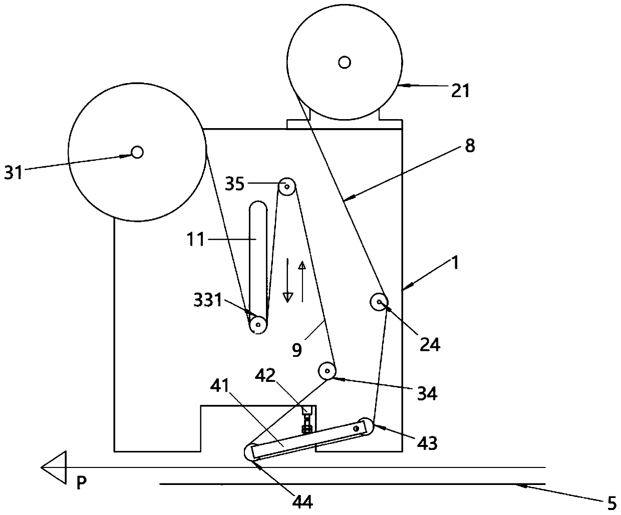
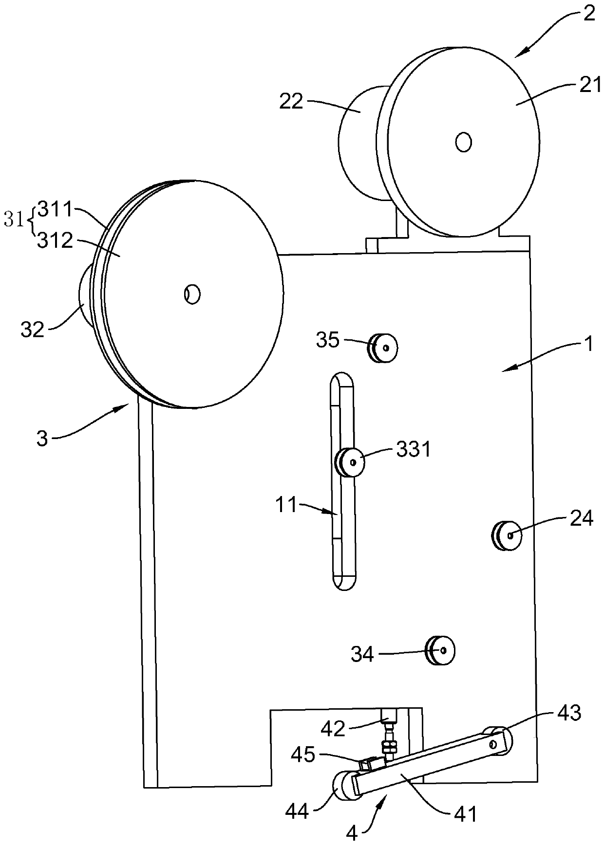
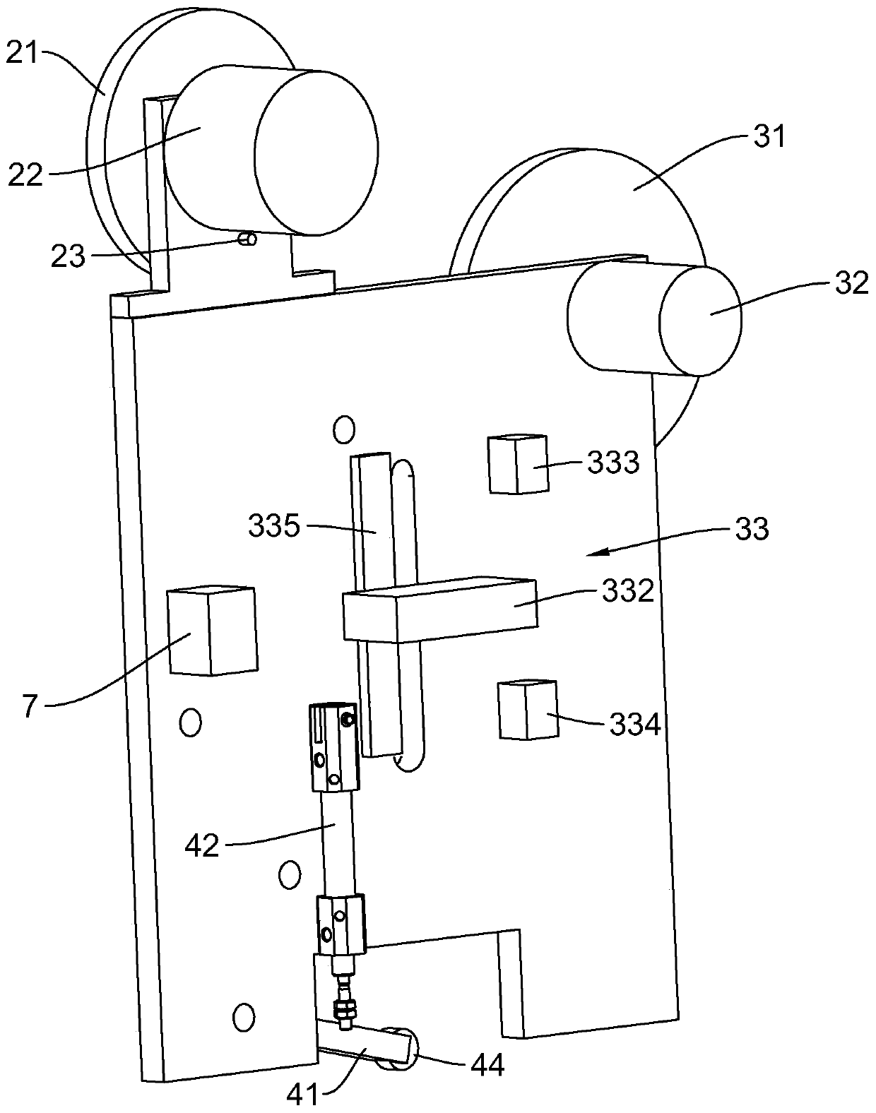
[0034] refer to Figure 1-3 , a narrow adhesive tape gluing device, including a mounting plate 1 arranged on the assembly line, the mounting plate 1 is provided with a discharge control mechanism 2, a material receiving control mechanism 3 and a gluing mechanism 4, and the gluing mechanism 4 It is located below the discharging control mechanism 2 and the receiving control mechanism 3; the adhesive tape is first unwound through the discharging control mechanism 2, and then the adhesive layer of the adhesive tape is separated from the release paper by the adhesive mechanism 4, and the adhesive layer is pasted on the On the edge of the mirror surface, the final release paper is rewound by the rewinding control...


PUM


Abstract

The invention relates to a narrow tape gluing device. The narrow tape gluing device comprises a mounting plate arranged on an assembly line, the mounting plate is provided with a discharging control mechanism, a receiving control mechanism and a gluing mechanism, the gluing mechanism is located below the discharging control mechanism and the receiving control mechanism, the receiving control mechanism is provided with a winding disc, a motor for controlling the winding disc in the winding of release paper, and a winding friction stabilizer for preventing the release paper from being broken, the winding friction stabilizer comprises a movable guide wheel capable of moving up and down, a balancing weight connected with the movable guide wheel, and an upper limit sensor and a lower limit sensor which are used for controlling the start or stop of the receiving control mechanism by sensing the upper limit and the lower limit of the balancing weight. The narrow tape gluing device is suitable for a narrow tape, can provide constant unwinding tension, can greatly reduce breakage times of a tape, and has good gluing effect; and the invention further provides a full-automatic mirror cabinet edge gluing machine based on the narrow tape gluing device.

Description

technical field [0001] The invention relates to the technical field of tape gluing equipment, in particular to a narrow tape gluing device suitable for narrow tape gluing and a fully automatic mirror cabinet edge gluing machine based on the narrow tape gluing device. Background technique [0002] The mirror cabinet is a kind of furniture with multiple functions such as mirroring and storage. The glass on the mirror cabinet usually needs to be pasted with 3M double-sided tape on its edge to fit closely with the frame of the mirror cabinet. The 3M double-sided tape consists of an adhesive layer and release paper composition. The bonding area between the glass edge and the frame of the mirror cabinet is small. In order to prevent glue leakage, the width of the 3M tape is generally controlled between 5-7mm. Adhesive tapes are generally applied by a gluing machine. Since the ordinary gluing machine uses a motor to control the unwinding and rewinding of the tape, it is generally ...

Claims


Application Information

Patent Timeline
Patent Type & Authority Applications(China)
IPC IPC(8): B65H37/04B65H16/00B65H35/07
CPCB65H16/00B65H35/0013B65H37/04
Inventor 梁武金伍朝军朱铁山
Owner 中山科勒卫浴有限公司
Why Eureka
Try Eureka