
Application of balloon bag quick to inflate and deflate in endotracheal catheter cuff

A tracheal tube, inflation and deflation technology, applied in the field of medical devices, can solve the problems of prolonging the rescue time, threatening the life safety of patients, complicated and complicated operation procedures, etc., and achieving the effects of convenient operation, strong practicability and simple structure

Inactive Publication Date: 2019-09-17
WUXI SHENGNUOYA TECH CO LTD
View PDF0 Cites 0 Cited by
  • Summary
  • Abstract
  • Description
  • Claims
  • Application Information

AI Technical Summary

Problems solved by technology

[0002] Endotracheal tube refers to the technology of inserting a special endotracheal tube into the trachea through the glottis. It is suitable for establishing an artificial airway for patients in clinical practice. Optimum conditions. The size and stability of the air bag on the endotracheal tube determine the success of the operation. At present, the inflation and deflation of the air bag needs to pass through an inflatable structure, and medical personnel need to manually measure the pressure and inflate and deflate. After inflation, it needs to be closed The airway has caused a certain amount of labor pressure for the medical staff, and the medical staff needs to observe the pressure of the pressure measuring ball in real time while inflating and deflating to observe the inflation situation. The operation process is cumbersome and complicated, and the rescue time is prolonged. life safety

Method used


Image

  • Application of balloon bag quick to inflate and deflate in endotracheal catheter cuff
  • Application of balloon bag quick to inflate and deflate in endotracheal catheter cuff
  • Application of balloon bag quick to inflate and deflate in endotracheal catheter cuff

Examples


Embodiment Construction

[0017] The present invention will be described in detail below in conjunction with the accompanying drawings and embodiments. It should be noted that the embodiments described above are only part of the embodiments of the present invention, rather than all implementation modes. Based on the embodiments of the present invention, the technical field All other embodiments obtained by persons of ordinary skill without creative efforts fall within the protection scope of the present invention.

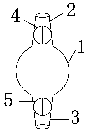
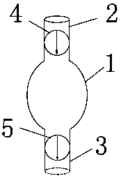
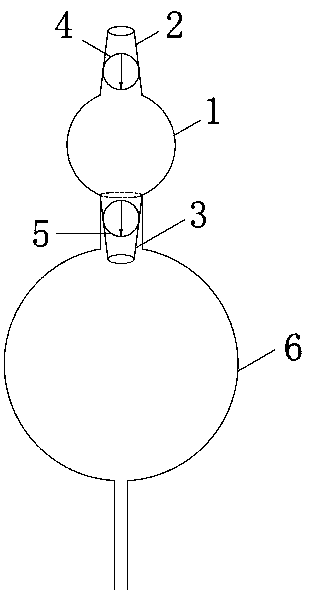
[0018] Such as figure 1 As shown, it is a schematic diagram of the structure of a rapid inflation and deflation balloon provided by the present invention. The rapid inflation and deflation balloon of the catheter includes an elastic balloon 1, and the two ends of the elastic balloon 1 are respectively fixed with a first elastic pipe 2 and a second elastic pipe 3, the first elastic pipe 2, the elastic balloon 1 and the second elastic pipe 3 are connected in turn to form a channel. The first...


PUM


Abstract

The invention relates to the technical field of medical apparatuses, in particular to an application of a balloon bag quick to inflate and deflate in an endotracheal catheter cuff. The balloon bag quick to inflate and deflate is used for controlling the inflating and deflating process of the endotracheal catheter cuff, the balloon bag quick to inflate and deflate comprises an elastic air bag; a first elastic pipeline and a second elastic pipeline are fixedly connected to the elastic air bag; a first one-way valve is arranged in the first elastic pipeline, and a second one-way valve is arranged in the second elastic pipeline; the direction of the first one-way valve is the same as that of the second one-way valve; and when the endotracheal catheter cuff needs inflating, the first one-way valve and the second one-way valve face an endotracheal catheter, and when the endotracheal catheter cuff needs deflating, the first one-way valve and the second one-way valve are back on to the endotracheal catheter. The balloon bag quick to inflate and deflate is simple in structure; and two one-way valves are arranged and applied to the endotracheal catheter cuff, so that quick inflating and deflating can be realized, manual labor pressure is reduced, the convenience of integrated operation of the endotracheal catheter is improved, and the practicality is high.

Description

technical field [0001] The invention relates to the technical field of medical appliances, in particular to the application of a rapidly inflatable and deflated balloon in an endotracheal catheter cuff. Background technique [0002] Endotracheal tube refers to the technology of inserting a special endotracheal tube into the trachea through the glottis. It is suitable for establishing an artificial airway for patients in clinical practice. Optimum conditions, the size and stability of the air bag on the endotracheal tube determine the success of the operation. At present, the inflation and deflation of the air bag needs to pass through an inflatable structure, and medical personnel need to manually measure the pressure and inflate and deflate. After inflation, it needs to be closed The airway has caused a certain amount of labor pressure for the medical staff, and the medical staff needs to observe the pressure of the pressure measuring ball in real time to observe the inflat...

Claims


Application Information

Patent Timeline
Patent Type & Authority Applications(China)
IPC IPC(8): A61M16/04
CPCA61M16/04A61M16/0402
Inventor 徐海英黑子清沈宁
Owner WUXI SHENGNUOYA TECH CO LTD
Learn More