Efficient noise reduction exhaust pipe

An exhaust pipe and noise technology, applied in the field of high-efficiency noise-reducing exhaust pipes, can solve the problems of a small number of thin-walled inner liner, obstructing airflow flow, and limited noise reduction effect, so as to increase the movement stroke and slow down the noise transmission. time, the effect of prolonging the reflection time

Pending Publication Date: 2019-09-13
HUZHOU XINXING AUTOMOBILE PARTS
View PDF1 Cites 2 Cited by
  • Summary
  • Abstract
  • Description
  • Claims
  • Application Information

AI Technical Summary

Problems solved by technology

[0003] For example: the Chinese utility model patent application number 201220053248.0 discloses a noise-reducing automobile exhaust pipe, including an exhaust pipe. The exhaust pipe is divided into three parts: an upper joint, a lower joint and a cylinder body. , The lower joint is funnel-shaped, and the exhaust pipe is provided with several mufflers and thin-walled inner tanks. The number of thin-walled inner tanks is small, and the noise reduction effect is limited, and the through holes on the thin-walled inner tanks are easily blocked, hindering the airflow flow

Method used


Image

  • Efficient noise reduction exhaust pipe
  • Efficient noise reduction exhaust pipe
  • Efficient noise reduction exhaust pipe

Examples


Embodiment 1

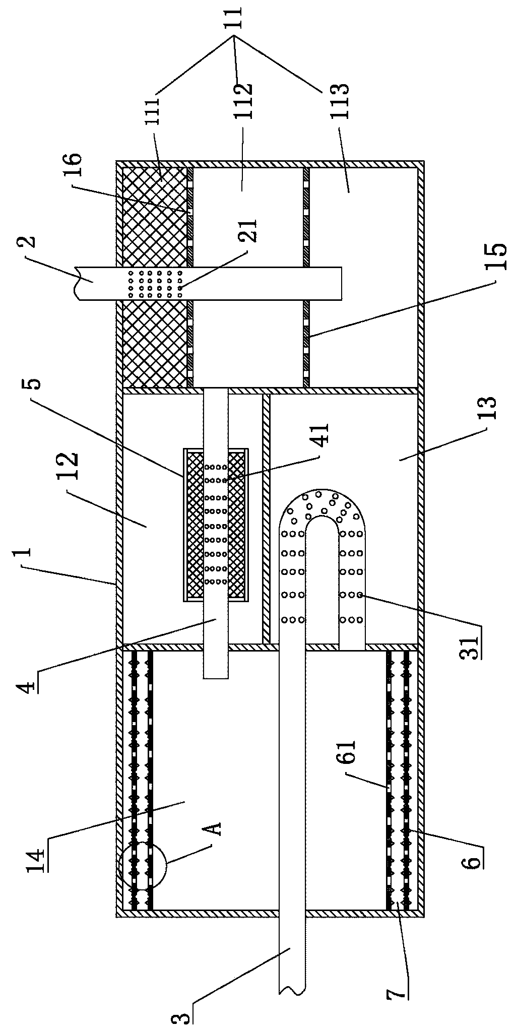
[0028] Embodiment 1: as figure 1 with figure 2 As shown, a high-efficiency noise-reducing exhaust pipe includes a cylinder body 1, an air intake pipe 2, an air outlet pipe 3 and a muffler pipe 4, and the cylinder body 1 is provided with an expansion chamber 11, a first resonance chamber 12, and a second resonance chamber 13 and the third resonant cavity 14, the expansion cavity 11 and the third resonant cavity 14 are located at both ends of the cylinder 1, and the first resonant cavity 12 and the second resonant cavity 13 are located in the middle of the cylinder 1.

[0029] The inlet pipe 2 communicates with the expansion chamber 11, the air outlet pipe 3 communicates with the third resonance chamber 14, the silencer pipe 4 is arranged in the first resonance chamber 12, and its two ends communicate with the expansion chamber 11 and the third resonance chamber 14 respectively, the silencer pipe 4 is provided with a first outlet hole 41 through which the muffler pipe 4 commun...

Embodiment 2

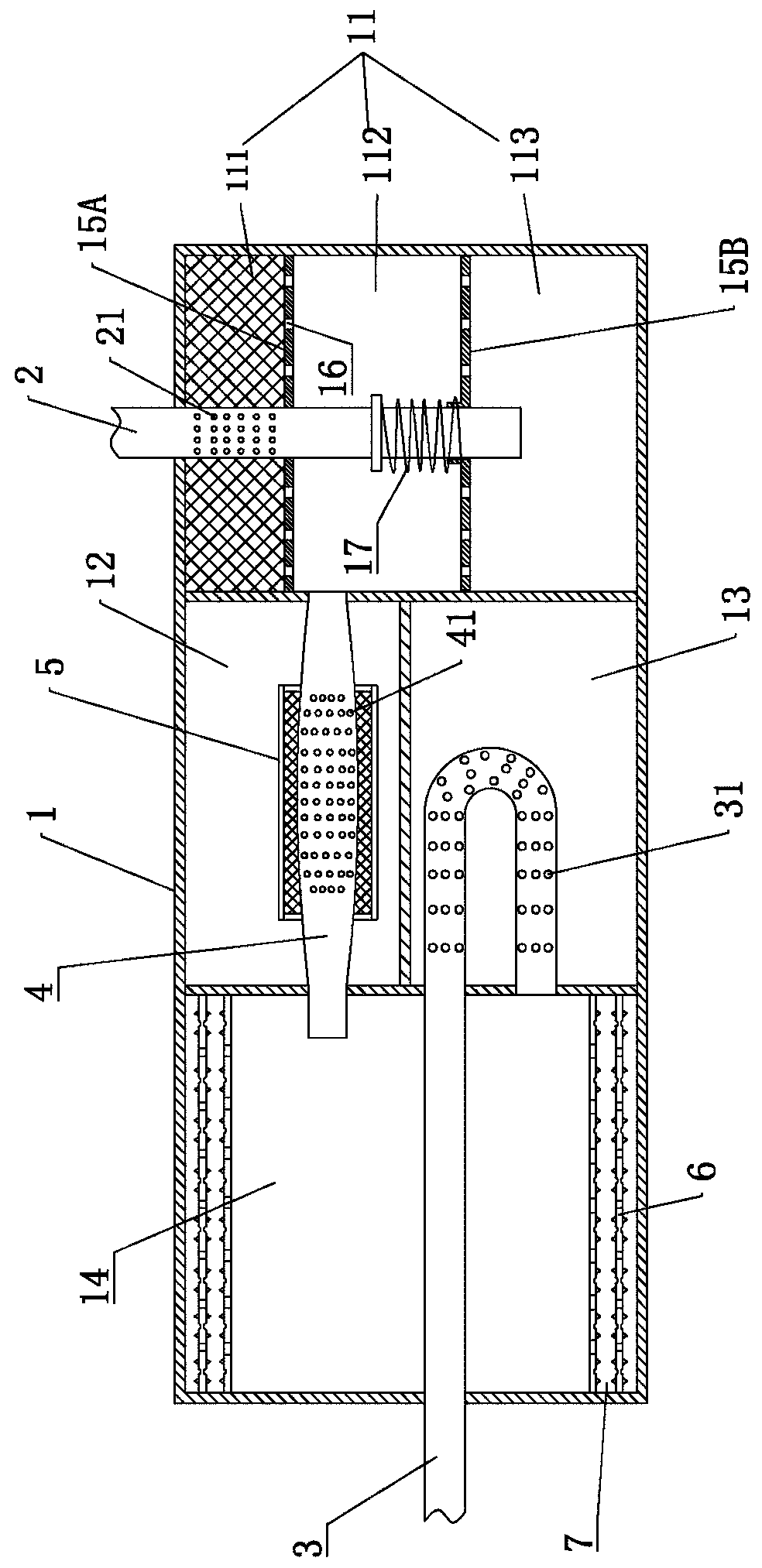
[0035] Embodiment 2: as image 3 As shown, the difference from Embodiment 1 is that the inner diameter of the muffler pipe 4 gradually increases from both ends to the middle, forming a drum-shaped structure.

[0036] The partition 15 is divided into a fixed partition 15A and a floating partition 15B. The fixed partition 15A is located between the first expansion chamber 111 and the second expansion chamber 112 and is fixed in the expansion chamber 11, and the floating partition 15B is located in the second expansion chamber. Between 112 and the third expansion chamber 113, the floating partition 15B is set on the intake pipe 2, and the second expansion chamber 112 is provided with an elastic reset member 17 that pushes the floating partition 15B to move away from the partition 15, elastically resets Part 17 is a spring.


PUM


Abstract

The invention relates to an efficient noise reduction exhaust pipe. The efficient noise reduction exhaust pipe comprises a cylinder, an air inlet pipe, an air outlet pipe and a noise reduction pipe; an expansion cavity, a first resonant cavity, a second resonant cavity and a third resonant cavity are formed in the cylinder, the air inlet pipe communicates to the expansion cavity, the air outlet pipe communicates with the third resonant cavity, the noise reduction pipe is arranged in the first resonant cavity, the two ends of the noise reducing pipe communicate with the expansion cavity and thethird resonant cavity, and a first outlet hole is formed in the noise reduction pipe; one part of the air outlet pipe extends into the second resonant cavity from the third resonant cavity, and is provided with a second outlet hole, and the other part penetrates through the third resonant cavity to the outer side of the cylinder from the second resonant cavity. In the treatment process of gas through the expansion cavity, the first resonant cavity, the second resonant cavity and the third resonant cavity, the motion stroke of noise is greatly prolonged, the noise transmission time is shortened, and the noise reduction effect is improved.

Description

technical field [0001] The invention relates to the technical field of automobile exhaust pipes, in particular to an efficient noise-reducing exhaust pipe. Background technique [0002] The exhaust pipe of a car has always been one of the main sources of vehicle noise. The noise is generally produced by the instability of high-speed air flow. The flowing airflow has the characteristics of high temperature, high pressure, and high speed. It emits high noise intensity, wide frequency spectrum, and wide range, which seriously affects the health of drivers and passengers and the production and life of residents. [0003] For example: the Chinese utility model patent application number 201220053248.0 discloses a noise-reducing automobile exhaust pipe, including an exhaust pipe. The exhaust pipe is divided into three parts: an upper joint, a lower joint and a cylinder body. , The lower joint is funnel-shaped, and the exhaust pipe is provided with several mufflers and thin-walled...

Claims


Application Information

Patent Timeline
IPC IPC(8): F01N13/08F01N13/00F01N1/02F01N1/08
CPCF01N13/08F01N13/007F01N1/02F01N1/089
Inventor 金建良张吉林梁成林
Owner HUZHOU XINXING AUTOMOBILE PARTS
Why Eureka
Try Eureka