Building steel structure suspension device

A construction steel and suspension technology, applied in the field preparation of building components, building structure, construction, etc., can solve the problems of increased safety hazards, damage to other items in the house, and reduced practicability, so as to improve practical reliability, Easy to use and simple structure

Active Publication Date: 2019-09-13
SUZHOU WEIZHONG TECH DEV CO LTD
View PDF19 Cites 0 Cited by
  • Summary
  • Abstract
  • Description
  • Claims
  • Application Information

AI Technical Summary

Problems solved by technology

[0002] Architectural steel structure has the functions of small space occupation, smart structure and easy disassembly and assembly. The building steel structure can be used to set up partitions, which improves the efficiency of space utilization on the one hand, and makes better use of the room on the other hand, and has the advantage of easy disassembly and assembly, and the traditional stairs with partitions carry out the work Among them, due to the inability to achieve more convenient structural changes, other items in the house will be damaged when carrying some items, which greatly reduces the working efficiency of the equipment and reduces the stability of the equipment during work. At the same time, due to the internal The structure is a fixed structure, which is extremely inconvenient when moving and installing, which reduces the practicability for personnel to use, and because of the reduced structural strength, it increases the safety hazards of subsequent use and threatens the safety of personnel

Method used


Image

  • Building steel structure suspension device
  • Building steel structure suspension device
  • Building steel structure suspension device

Examples


Embodiment Construction

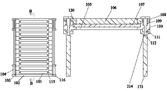
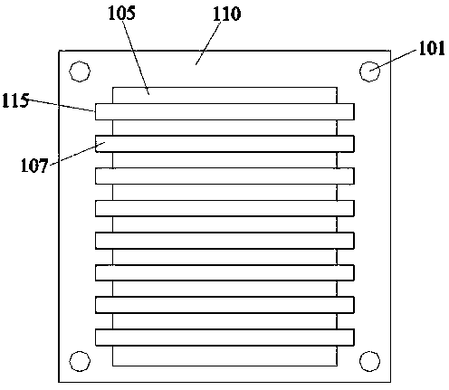
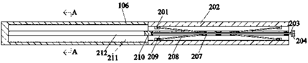
[0023] Such as Figure 1-Figure 6 As shown, the present invention is described in detail. For the convenience of description, the orientations mentioned below are now stipulated as follows: figure 1 The up, down, left, right, front and back directions of the projection relationship itself are consistent. A building steel structure suspension device of the present invention includes a support frame 110. An open cavity 115 is arranged in the support frame 110. The lower end wall of the cavity 115 communicates with An inner chamber 105 is provided, and the lower end surface of the support frame 110 is provided with left-right symmetrical support feet 113, and an opening matching cavity 111 is arranged in the support feet 113, and a matching cavity 111 is provided in the lower end wall of the matching cavity 111 to communicate with each other. Threaded hole 114, the support frame 110 is clamped and connected with the matching cavity 111, and a plurality of support cylinders 107 ar...


PUM


Abstract

The invention discloses a building steel structure suspension device. The building steel structure suspension device comprises a supporting frame. An open accommodating cavity is formed in the supporting frame. An inner cavity is formed in the lower end wall of the accommodating cavity in a communicating mode, and supporting foot margins which are symmetrically left and right are arranged on the lower end surface of the supporting frame, wherein open matching cavities are formed in the supporting foot margins, matching threaded holes are formed in the lower end walls of the matching cavities in a communicating mode, and the supporting frame is in fit connection with the matching cavities in an installing and clamping mode, a plurality of supporting cylinders are arranged in the accommodating cavity in an installing and clamping mode, flat plate devices for unfolding to form a tiling structure are arranged on the upper end surfaces of the supporting cylinders, and cover plates are fixedly arranged on the upper end surface of the supporting frame. The building steel structure suspension device has a simple structure, the structure of the flat plate devices and ladder devices is adopted, so that the device has the function of easy disassembling and quick unfolding, the device is easily carried, the personnel can conveniently carry articles to a high place, the building steel structure suspension device has the characteristics of convenient use by personnel, and the practical reliability of the device is greatly improved.

Description

technical field [0001] The invention relates to the technical field of building steel structures, in particular to a building steel structure suspension device. Background technique [0002] Architectural steel structure has the functions of small space occupation, smart structure and easy disassembly and assembly. The building steel structure can be used to set up partitions, which improves the efficiency of space utilization on the one hand, and makes better use of the room on the other hand, and has the advantage of easy disassembly and assembly, and the traditional stairs with partitions carry out the work Among them, due to the inability to achieve more convenient structural changes, other items in the house will be damaged when carrying some items, which greatly reduces the working efficiency of the equipment and reduces the stability of the equipment during work. At the same time, due to the internal The structure is a fixed structure, which is extremely inconvenient...

Claims


Application Information

Patent Timeline
Patent Type & Authority Applications(China)
IPC IPC(8): E04G27/00
CPCE04G27/00
Inventor 不公告发明人
Owner SUZHOU WEIZHONG TECH DEV CO LTD
Why Eureka
Try Eureka