Triaxial planeness detection system and triaxial planeness detection method

A technology of detection system and axis plane, which is applied to measurement devices, instruments, and optical devices, etc., can solve the problems of deviation of measurement results and reduce measurement efficiency, and achieve the effect of improving accuracy and improving measurement efficiency.

Inactive Publication Date: 2019-09-10
江苏省百斯特检测技术有限公司
View PDF10 Cites 6 Cited by
  • Summary
  • Abstract
  • Description
  • Claims
  • Application Information

AI Technical Summary

Problems solved by technology

[0004] In the prior art, the laser method only has one axis. Based on this axis, only one surface can be measured at a time. When the workpiece is cubic and all sides need to meet the predetermined flatness, the disadvantages of this detection system will appear. After measuring a surface, it is necessary to manually take out the workpiece, and then change the surface to reposition and continue the measurement, which undoubtedly reduces the overall measurement efficiency; at the same time, the existing technology uses a laser measuring instrument to move while the workpiece is fixed. The method relies on the laser measuring instrument to continuously move to measure the height difference on the surface of the workpiece. When the laser measuring instrument moves, because the laser is shot from the laser source to the workpiece, the tiny vibration will be amplified, which will greatly affect the measurement results. deviation

Method used


Image

  • Triaxial planeness detection system and triaxial planeness detection method
  • Triaxial planeness detection system and triaxial planeness detection method
  • Triaxial planeness detection system and triaxial planeness detection method

Examples


Embodiment Construction

[0039] In the following description, numerous specific details are given in order to provide a more thorough understanding of the present invention. It will be apparent, however, to one skilled in the art that the present invention may be practiced without one or more of these details. In other examples, some technical features known in the art are not described in order to avoid confusion with the present invention.

[0040] In the description of the present invention, it should be noted that the terms "center", "upper", "lower", "left", "right", "vertical", "horizontal", "inner", "outer" etc. The indicated orientation or positional relationship is based on the orientation or positional relationship shown in the drawings, and is only for the convenience of describing the present invention and simplifying the description, rather than indicating or implying that the referred device or element must have a specific orientation, or in a specific orientation. construction and oper...


PUM


Abstract

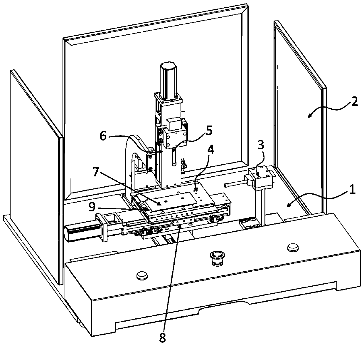
The invention relates to a triaxial planeness detection system and a triaxial planeness detection method. The system comprises four parts including a basic component, a triaxial sliding mechanism, a workpiece locating platform and a laser measurement component. The triaxial sliding mechanism comprises a cross-shaped sliding table and a vertical sliding table, and the cross-shaped sliding table drives a detected workpiece to move in a horizontal range and works in cooperation with a laser measurement instrument. A measurement mode in which the workpiece moves and the laser measurement instrument is stationary is used, thus, accuracy of a measurement result is improved, and a problem that the measurement is not accurate enough when the laser measurement instrument moves and even micro vibration can cause large deviation of the measurement result is solved. The laser measurement component comprises three groups of the laser measurement instruments of which laser emitting extension lines mutually form a 90-degree included angle. By coordinated cooperation of the triaxial sliding mechanism and the laser measurement instruments, the system provided by the invention can complete measurement of side face and upper surface planeness of the measured workpiece in one work procedure, and thus, measurement efficiency is improved.

Description

technical field [0001] The invention relates to a flatness detection system, in particular to a three-axis flatness detection system and a detection method thereof. Background technique [0002] The flatness error is to compare the measured actual surface with the ideal plane, and the line value distance between the two is the flatness error value; or by measuring the relative height difference of several points on the actual surface, and then converting it to the line value Flatness error value. The more common flatness measurement methods usually include metering method and laser method. The metering method is to place the measured part and the micrometer on the standard flat plate, use the standard flat plate as the measurement reference surface, and use the micrometer along the The actual surface is measured point by point or along several straight lines. The laser method uses laser ranging to perceive the distance of each point, and then judges its flatness. [0003]...

Claims


Application Information

Patent Timeline
Patent Type & Authority Applications(China)
IPC IPC(8): G01B11/30
CPCG01B11/30
Inventor 潘东林慧娟
Owner 江苏省百斯特检测技术有限公司
Why Eureka
Try Eureka