Gas pipe movable connection valve with multiple seals
A technology of multiple seals and gas pipes, used in shaft seals, threaded connections, engine seals, etc., to improve sealing performance, facilitate installation, and prevent gas leakage
- Summary
- Abstract
- Description
- Claims
- Application Information
AI Technical Summary
Problems solved by technology
Method used
Image

Examples
Embodiment 1
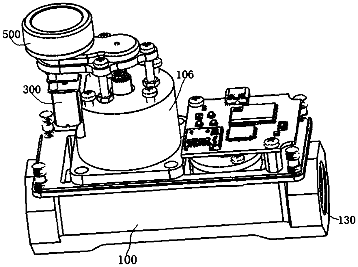
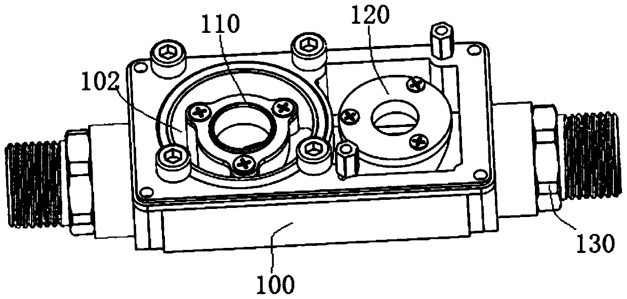
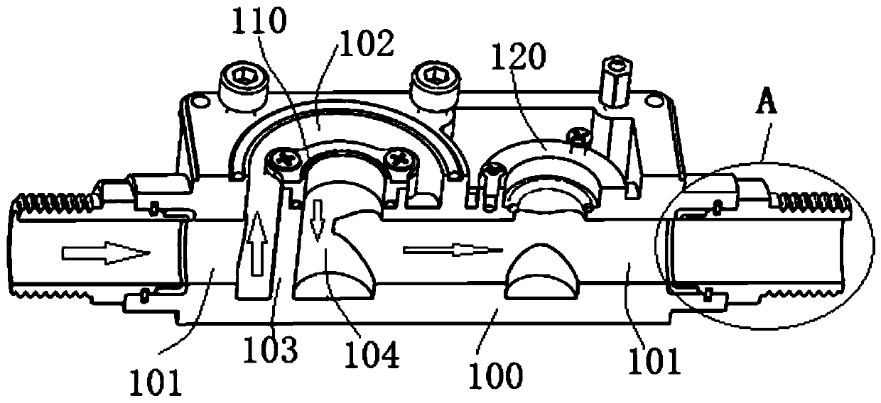
[0045] Such as Figure 1-Figure 9 As shown, a gas pipe union valve with multiple seals in this embodiment includes a valve body 100, an outer shell 105 is provided on the outside of the valve body 100 to cover the internal overall structure, and a valve body 100 is provided with a valve for gas circulation. However, the main flow chambers 101 located on the front and rear sides of the sealing interface are not directly connected, but the main flow chambers 101 are respectively opened in the front and back, and the inner sealing cylinder 103 is arranged in the sealing interface, and the inner sealing cylinder 103 and the front end of the valve body 100 (Such as image 3 The gap between the main flow chambers 101 on the left side in the orientation) is the outer flow chamber 102, and the inner seal cylinder 103 is provided with an inner flow chamber 104, and the inner flow chamber 104 is connected to the rear end of the valve body 100 (such as image 3 The main flow cavity 101 ...
Embodiment 2
[0053] A gas pipe union valve with multiple seals in this embodiment is basically the same as the above embodiment, further, as Figure 7 As shown, the double-chamber sealing ring 400 in this embodiment includes an inner ring body 410 for compressing and sealing the inner flow chamber 104. The diameter of the inner ring body 410 is larger than the diameter of the inner flow chamber 104. The outer side of the inner ring body 410 is An outer ring body 420 with an inverted U-shaped cross-section is arranged around the circumference. The outer ring body 420 is set above the outer flow chamber 102. The outer edge of the outer ring body 420 is also provided with an outward extension section, which is embedded in the end cap for sealing. The inner side of the cover 106, and the bottom of the extension section is provided with a circle of lower convex section 421, the lower convex section 421 is embedded into the valve body 100 below; the extension section is also provided with an inne...
Embodiment 3
[0056]A gas pipe live connection valve with multiple seals in this embodiment is basically the same as the above-mentioned embodiment. Further, the upper end of the inner sealing cylinder 103 in this embodiment is provided with a sealing interface cover 110, and the sealing interface cover 110 is connected to the inner sealing cylinder. A sealing ring 112 is arranged between the side walls of 103, and the side wall of the inner chamber of the sealing interface cover 110 is flush with the side wall of the inner circulation chamber 104 of the inner sealing cylinder 103. The valve body 100 includes the inner sealing cylinder 103. In the industry, casting is usually used. Its processing accuracy is difficult to meet the gas sealing requirements of this embodiment. By separately setting the sealing interface cover 110 on the upper end of the inner sealing cylinder 103, the processing accuracy of the product can be effectively improved and the sealing performance can be ensured. The ...
PUM
 Abstract
Description
Claims
Application Information
 - R&D
- Intellectual Property
- Life Sciences
- Materials
- Tech Scout
- Unparalleled Data Quality
- Higher Quality Content
- 60% Fewer Hallucinations
Browse by: Latest US Patents, China's latest patents, Technical Efficacy Thesaurus, Application Domain, Technology Topic, Popular Technical Reports.
© 2025 PatSnap. All rights reserved.Legal|Privacy policy|Modern Slavery Act Transparency Statement|Sitemap|About US| Contact US: help@patsnap.com