A head and tail yarn automatic isolation system

A technology of isolation system and head and tail filaments, which is applied in the direction of filament generation, spinneret assembly, textiles and papermaking, etc., can solve the problems of large application restrictions and poor detection effect of head and tail filaments, and achieve small application restrictions and benefit Productivity and the effect of expanding the range of applications

Active Publication Date: 2020-11-13
WUHAN TEXTILE UNIV +2
View PDF5 Cites 0 Cited by
  • Summary
  • Abstract
  • Description
  • Claims
  • Application Information

AI Technical Summary

Problems solved by technology

[0005] The purpose of the present invention is to overcome the defects and problems of poor head and tail silk detection effect and relatively large application restrictions in the prior art, and provide a head and tail silk automatic isolation with good head and tail silk detection effect and small application restrictions system

Method used


Image

  • A head and tail yarn automatic isolation system
  • A head and tail yarn automatic isolation system
  • A head and tail yarn automatic isolation system

Examples


Embodiment 1

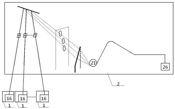
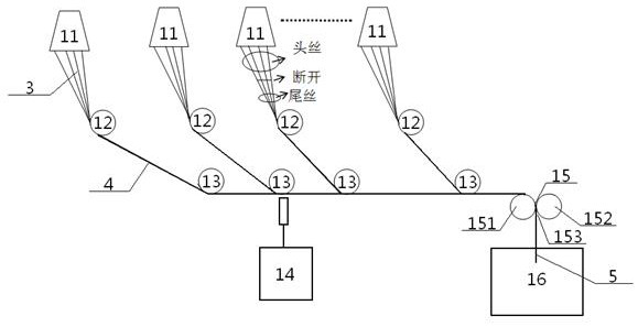
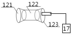
[0046] see Figure 1 to Figure 4 , an automatic isolation system for head and tail threads; the automatic isolation system includes a front unit 1 and a rear unit 2, a single rear unit 2 corresponds to at least two front units 1, and only one container is arranged in a single front unit 1 Silk barrel 16; the pre-unit 1 includes a raw silk nozzle 11, a godet wheel 12, a threading device 14, a traction wheel 15 and a silk barrel 16, and the number of the raw silk nozzle 11 and the godet wheel 12 is multiple , and one-to-one correspondence; the downstream of the raw silk nozzle 11 is a godet 12, the godet 12 is provided with a speed detection device 17, the downstream of the godet 12 is a traction wheel 15, and the downstream of the traction wheel 15 is Silk barrel 16; the rear unit 2 includes a cluster wheel 21, the first drafting wheel 22 and a packing device 26, the upstream of the cluster wheel 21 is the silk barrel 16 in the front unit 1, and the downstream of the cluster wh...

Embodiment 2

[0048] Basic content is the same as embodiment 1, the difference is:

[0049] Be provided with bunching wheel 13 between described godet wheel 12 and traction wheel 15, the quantity of bunching wheel 13 corresponds to godet wheel 12 one by one, the downstream of godet wheel 12 is bunching wheel 13, and this bunching wheel The downstream of 13 is traction wheel 15. The spinning-in device 14 is arranged close to the raw silk spraying head 11 .

Embodiment 3

[0051] Basic content is the same as embodiment 1, the difference is:

[0052] Below the first drafting wheel 22, a counter 27 for the number of rotations is arranged.


PUM


Abstract

An automatic isolation system for head and tail filaments comprises front units and rear units. A single rear unit corresponds to at least two front units, and only one filament barrel is arranged ina single front unit. Each front unit comprises a plurality of raw filament nozzles, a plurality of filament guide wheels, a raw head device, a traction wheel and the filament barrel. The raw filamentnozzles and the filament guide wheels are in one-to-one correspondence. The filament guide wheels are located at downstream positions of the raw filament nozzles. Speed detectors are arranged on the filament guide wheels. The traction wheels are located at downstream positions of the filament guide wheels. The filament barrels are located at downstream positions of the traction wheels. Each rear unit comprises a bundle collection wheel, a first drafting wheel and a packaging device. The filament barrels of the front units are located at upstream positions of the bundle collection wheels, the first drafting wheels are located at downstream positions of the bundle collection wheels, and the packaging devices are located at downstream positions of the first drafting wheels. The automatic isolation system has the advantages of good detection effect on the head and tail filaments, less application limitation and small application range.

Description

technical field [0001] The invention relates to a device for removing head and tail threads, in particular to an automatic isolation system for head and tail threads, which is particularly suitable for improving the detection effect of head and tail threads and reducing application restrictions. Background technique [0002] At present, in the production process of spraying fiber filaments with nozzles, head and tail filaments will be produced due to the problems of raw materials and production processes. There are two main reasons for this. One is that the raw materials will gather at the spinneret and form silk threads. The defect is that the workers repair the board regularly, and at this time the fibers will be cut off, resulting in head and tail threads; the second is that the production line fails due to other reasons, resulting in the breakage of the fiber threads, which will also produce head and tail threads. [0003] The existence of head and tail filaments will ca...

Claims


Application Information

Patent Timeline
Patent Type & Authority Patents(China)
IPC IPC(8): D01D4/02D01D11/04D01D13/02
CPCD01D4/025D01D11/04D01D13/02
Inventor 李德骏吴宛萍邹崇涛薛文伟方涵李宇纪昌俊郑力文袁浩然林东刘会清李广龙
Owner WUHAN TEXTILE UNIV
Why Eureka
Try Eureka