
Small-sized assembly line type paint spraying room special for machining automobile mechanical parts

A kind of mechanical parts and assembly line technology, applied in the direction of spraying booths, spraying devices, etc., can solve problems such as jamming, spraying paint diffusion, poor paint protection ability, etc., to achieve the effect of protecting the working environment, increasing the recovery speed, and protecting the painting environment

Active Publication Date: 2019-09-10
乐清市曙晟科技有限公司
View PDF6 Cites 6 Cited by
  • Summary
  • Abstract
  • Description
  • Claims
  • Application Information

AI Technical Summary

Problems solved by technology

[0006] To sum up, the present invention provides a small assembly-line paint spraying booth dedicated to the processing of automotive machinery parts. Through structural and functional improvements, it solves the problem that the structure is simple, generally does not have the function of multi-directional spraying, and when the paint spraying booth is used in an assembly line Poor sealing, poor protection ability for sprayed paint, easy to cause bad phenomena such as spray paint diffusion, and does not have cleaning function for spray paint contaminated on the assembly line, which may cause jamming after long-term use, which is not conducive to safe use.

Method used


Image

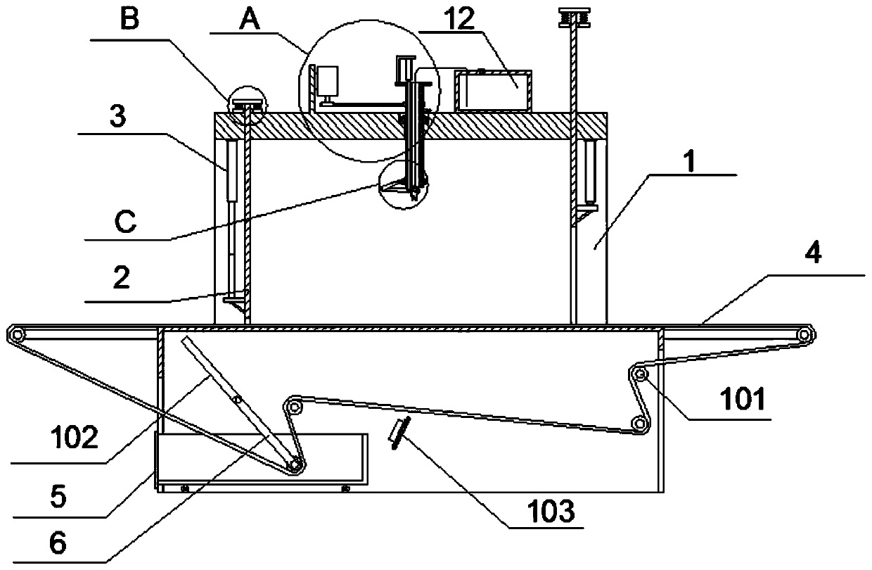
  • Small-sized assembly line type paint spraying room special for machining automobile mechanical parts
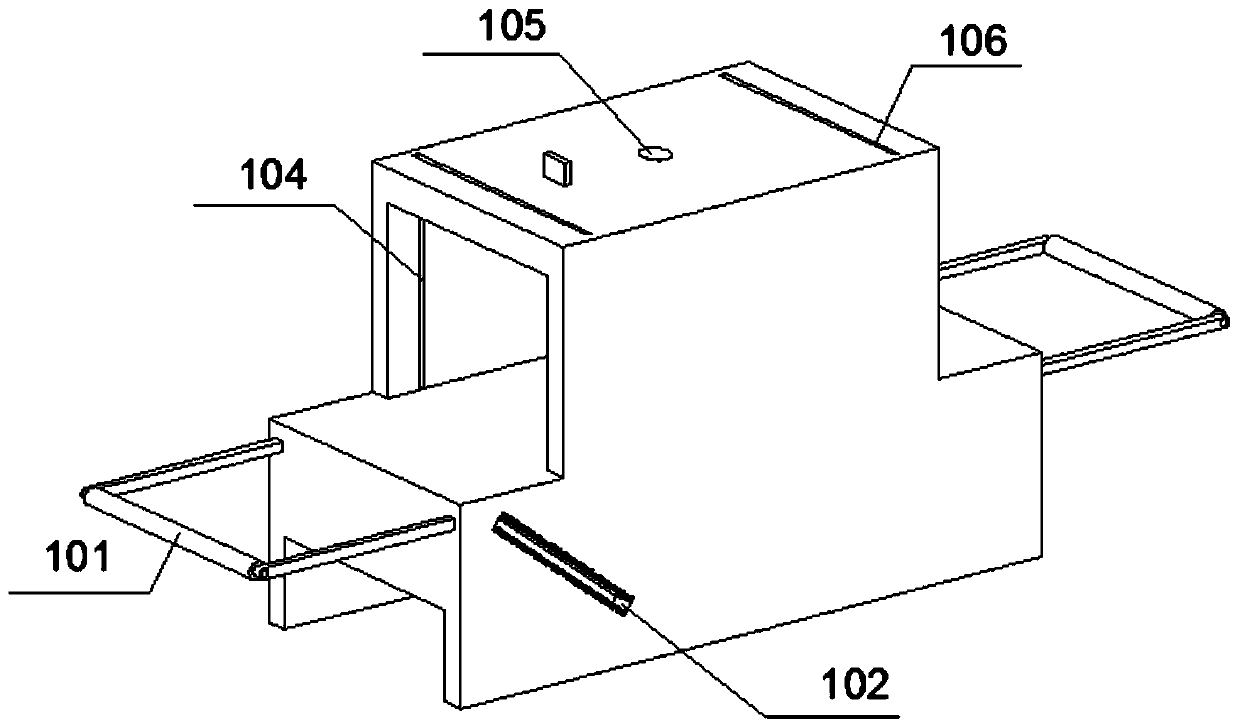
  • Small-sized assembly line type paint spraying room special for machining automobile mechanical parts
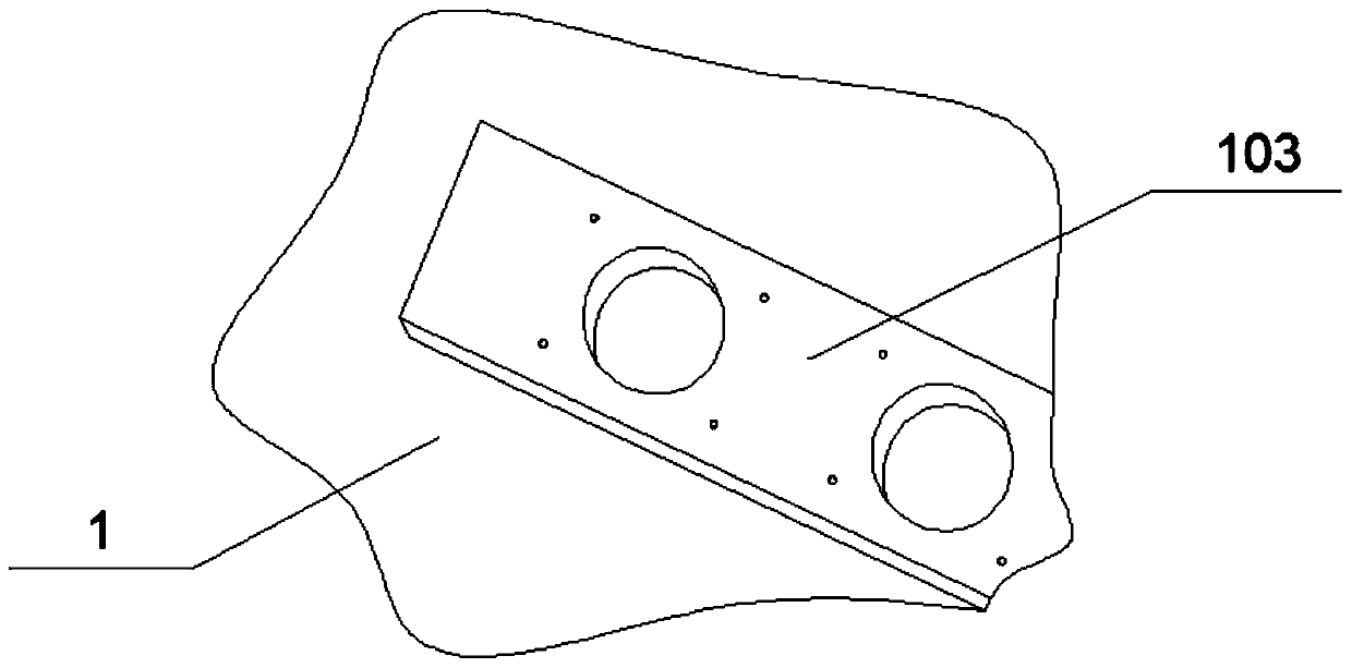
  • Small-sized assembly line type paint spraying room special for machining automobile mechanical parts

Examples


Embodiment Construction

[0032] Embodiments of the present invention will be further described in detail below in conjunction with the accompanying drawings and examples. The following examples are used to illustrate the present invention, but should not be used to limit the scope of the present invention.

[0033] In the description of the present invention, unless otherwise stated, the meaning of "plurality" is two or more; the terms "upper", "lower", "left", "right", "inner", "outer" , "front end", "rear end", "head", "tail", etc. indicate the orientation or positional relationship based on the orientation or positional relationship shown in the drawings, and are only for the convenience of describing the present invention and simplifying the description, rather than Nothing indicating or implying that a referenced device or element must have a particular orientation, be constructed, and operate in a particular orientation should therefore not be construed as limiting the invention. In addition, t...


PUM


Abstract

The invention provides a small-sized assembly line type paint spraying room special for machining automobile mechanical parts. The small-sized assembly line type paint spraying room comprises a paintspraying room shell, a conveyor belt guide wheel, an air cylinder A, a conveyor belt, an air cylinder B, a pull rod, an automatic spray gun head and a paint box, wherein five conveyor belt guide wheels are fixedly arranged at the inner side and the inner side of the bottom of outer support structures at the two ends of the paint spraying room shell through rotating shafts, and the conveyor belt isarranged outside the conveyor belt guide wheels; one of the rotating shafts of the conveyor belt guide wheels is fixedly connected through a key, and a motor is arranged on the outer sides of the conveyor belt guide wheels and is in motion connection with the conveyor belt guide wheels through transmission of a belt. Through arrangement of a the paint plate and the air cylinder A, the paint spraying room shell can be controllably sealed, the paint spraying environment is protected, the situation that the paint spraying is sprayed too much to cause pollution to the outside is avoided, and theworking environment is protected; and in addition, due to arrangement of stretchable rods and annular spring-assisting plates, favorable help is provided for the retraction of the air cylinder A, theretraction speed of the air cylinder A can be increased through the elasticity of springs, and the running speed of flowing water can be effectively increased.

Description

technical field [0001] The invention relates to the technical field of auto parts, and more specifically, to a small-scale assembly-line spray booth dedicated to the processing of auto mechanical parts. Background technique [0002] Auto parts are the units that constitute the overall processing of auto parts and the products that serve the processing of auto parts. They are made of a variety of different materials according to the requirements and functions of the use. Generally, a layer of paint will be sprayed on the surface of the auto parts after the production is completed. The effect of protecting the car is usually carried out in the spray booth. [0003] Based on the above, the inventors found that the commonly used paint spraying booths are simple in structure, generally do not have the function of multi-directional spraying, and the spraying booths are poorly sealed when used in the assembly line, and have poor protection for the sprayed paint, which is likely to ...

Claims


Application Information

Patent Timeline
Patent Type & Authority Applications(China)
IPC IPC(8): B05B13/02B05B16/40B05B15/68B05B13/04B05B15/55
CPCB05B13/0421B05B15/55B05B15/68B05B16/40B05B16/95
Inventor 孙梨梨
Owner 乐清市曙晟科技有限公司
Learn More