Brain electrode fixation device and suite

A fixing device and electrode technology, applied in the direction of internal electrodes, head electrodes, electrodes, etc., can solve problems such as cranial hole ring prolapse, inability to disassemble, and affect the image of patients, so as to achieve the effect of ensuring aesthetics and easy disassembly

Pending Publication Date: 2019-09-10
SCENERAY
View PDF1 Cites 6 Cited by
  • Summary
  • Abstract
  • Description
  • Claims
  • Application Information

AI Technical Summary

Problems solved by technology

[0004] The brain electrode fixing device in the prior art has the following disadvantages: 1. The thickness of the existing cranial hole ring is too thick. The bottom of the cranial hole ring is flat, and it cannot fit the curved skull during implantation, and the phenomenon of two ends warping occurs, which affects the image of the patient; 3. The existing cranial hole ring is designed as an opening, and it is plugged into the 14mm cranial hole through interference deformation. The purpose of fixation is achieved, but during the operation, the doctor often opens the hole, and the existing cranial hole ring often comes out of the cranial hole during the operation; 4. The existing cranial hole cover is difficult to disassemble, and often cannot be disassembled or directly removed broken

Method used


Image

  • Brain electrode fixation device and suite
  • Brain electrode fixation device and suite
  • Brain electrode fixation device and suite

Examples


Embodiment Construction

[0038] The specific implementation manners of the present invention will be further described in detail below in conjunction with the accompanying drawings and embodiments. The following examples are used to illustrate the present invention, but are not intended to limit the scope of the present invention.

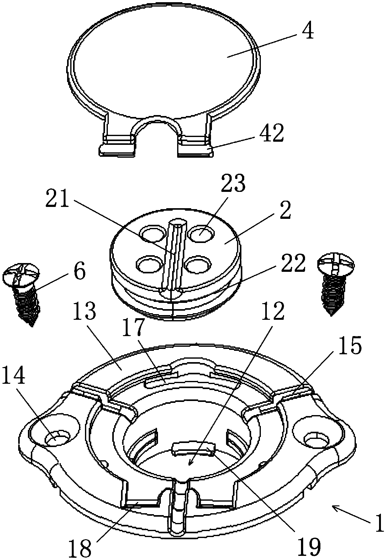
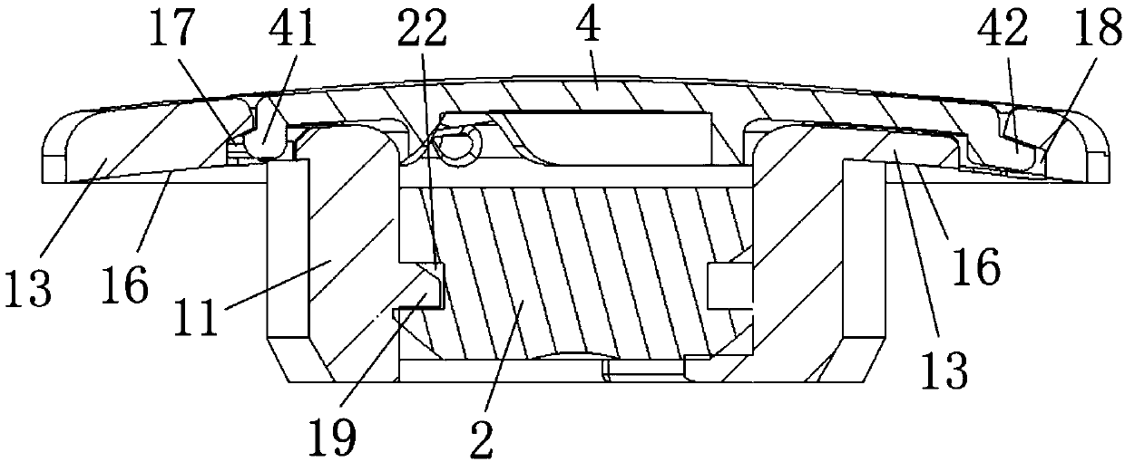
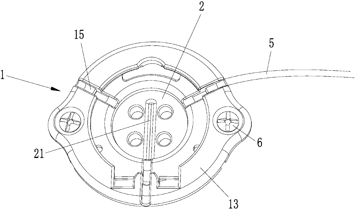
[0039] Reference attached figure 1 to attach Image 6 , a brain electrode fixing device, which includes a cranial hole ring 1, a cranial hole electrode lock 2, and a cranial hole cover 4.

[0040] The cranial hole ring 1 includes a cranial hole joint 11 for fixing it on the cranial hole, an electrode hole 12 that is opened at the center of the cranial hole joint 11 and is used to pass through the brain electrode 5, along the cranial hole joint 11. The circumferentially outwardly extending ring portion 13 .

[0041] The bottom surface 16 of the ring part 13 is a curved surface and fits the skull so that it fits the curved skull better during implantation, ensuring the ov...


PUM

PropertyMeasurementUnit
Thicknessaaaaaaaaaa
Thicknessaaaaaaaaaa

Abstract

The invention discloses a brain electrode fixation device and suite. The fixation device includes a cranial hole ring, a cranial hole electrode lock, and a cranial hole cover; the cranial hole ring includes a cranial hole junction portion for fixing the cranial hole ring to a cranial hole, an electrode hole disposed on a central portion of the cranial hole junction portion and used for passing through a brain electrode, and a ring portion extending outwardly along a circumferential direction of the cranial hole junction portion, a bottom surface of the ring portion is a cambered surface and the ring portion is attached to cranium, and at least two screw connection holes are disposed on the ring portion, and the ring portion is fixed to the cranium by screws; the cranial hole electrode lockis disposed in the electrode hole, and the cranial hole electrode lock is provided with at least one groove used for penetrating through and clamping the brain electrode; and the cranial hole cover is connected with the cranial hole ring and enables the cranial hole electrode lock to be enclosed in the electrode hole. In the brain electrode fixation device and suite, the thickness of the cranialhole ring is thinner than that of the prior art, and protrusion of an obvious convex bulge in scalp of a patient is prevented after implantation; and the bottom surface of the ring portion is the cambered surface, the ring portion is more closely attached to the cranium with radian during the implantation, and the whole aesthetic property is ensured.

Description

technical field [0001] The invention belongs to the field of implantable medical systems, in particular to a brain electrode fixing device and a kit. Background technique [0002] Implantable medical systems usually include implantable nerve electrical stimulation systems, implantable cardiac electrical stimulation systems (commonly known as cardiac pacemakers), and implantable drug infusion systems. Among them, the implantable electrical nerve stimulation system includes deep brain electrical stimulation DBS, implantable cerebral cortex electrical stimulation CNS, implantable spinal cord electrical stimulation SCS, implantable sacral nerve electrical stimulation SNS, and implantable vagus nerve electrical stimulation VNS. Taking the implanted electrical nerve stimulation system as an example, it mainly includes a pulse generator implanted in the body, electrodes and external control devices. Among them, the pulse generator is connected to the electrode, so that the pulse g...

Claims


Application Information

Patent Timeline
IPC IPC(8): A61N1/05
CPCA61N1/0539A61N1/3605A61N1/375A61N1/0531A61N1/0534
Inventor 张磊
Owner SCENERAY
Why Eureka
Try Eureka