
Linear chamfer cable stripping device

A beveling line and straight line technology, applied in the field of straight beveling cable stripping device, can solve the problems of high cost and poor controllability, etc., and achieve the effect of good controllability and high-precision cutting

Pending Publication Date: 2019-09-06
AMPHENOL ELECTRONICS ASSEMBLY XIAMEN CO LTD
View PDF0 Cites 0 Cited by
  • Summary
  • Abstract
  • Description
  • Claims
  • Application Information

AI Technical Summary

Problems solved by technology

At present, the mechanical cutting and peeling methods of flat cables, multi-layer data cables, flexible cables, SFC and other soft and tough flat cables at home and abroad are vertical vertical pressure cutting or circular saw cutting or peeling. Laser cutting has certain limitations on precision and soft materials or high cost and poor controllability

Method used


Image

  • Linear chamfer cable stripping device
  • Linear chamfer cable stripping device
  • Linear chamfer cable stripping device

Examples


Embodiment Construction

[0023] The present invention will be further described below in conjunction with the accompanying drawings and specific embodiments.

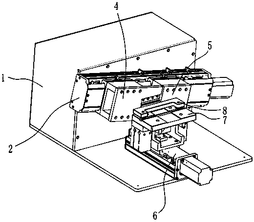
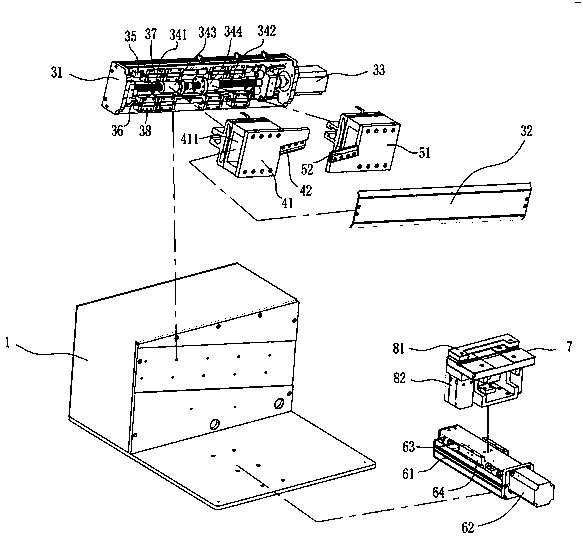
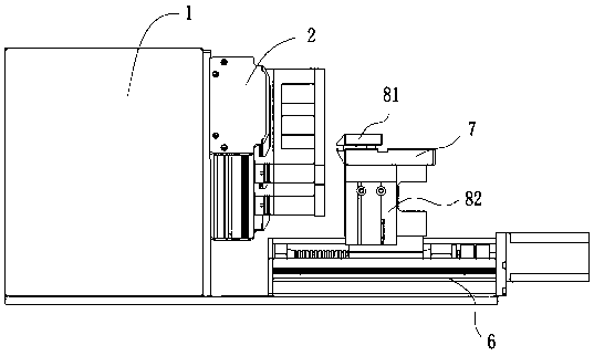
[0024] Such as Figure 1 ~ Figure 3 As shown, the present invention discloses a linear bevel cutting cable stripping device, comprising: a control box 1 , a linear bevel cutting module 2 , a linear guide rail module 6 , an object stage 7 and a clamp 8 .

[0025] The control box 1 is used to control the electrical actions of the linear beveling module 2 , the linear guide rail module 6 and the fixture 8 .

[0026] The linear bevel cutting module 2 is installed on the vertical surface, and the linear bevel cutting module 2 can be directly installed on the vertical surface of the control box 1. The linear guide rail module 6 is installed on a horizontal plane. The stage 7 is arranged horizontally and connected with the linear guide module 6, and the clamp 8 is arranged above the stage 7 for clamping the cables.

[0027] The linear bevel cutting...


PUM


Abstract

The invention discloses a linear chamfer cable stripping device comprising a control box, a linear chamfer module, a linear guide rail module, an object table and a clamp. The linear chamfer module ismounted on a vertical surface. The linear guide rail module is mounted on a horizontal plane. The object table is horizontally arranged to be connected with the linear guide rail module. The clamp isarranged on the object table for clamping the cable. The linear chamfer module comprises an oblique guide rail group, a first knife group and a second knife group. An acute angle is formed between the oblique guide rail group and the horizontal plane. The first knife group and the second knife group are mounted on the oblique guide rail group and can move in an opposing or opposite direction along the oblique guide rail group. The cable on the object table is controlled to move to the position between the first knife group and the second knife group by the linear guide rail module. Simultaneous cutting in the horizontal and vertical directions can be realized in the movement and the cutting precision is high.

Description

technical field [0001] The invention relates to cable stripping equipment, in particular to a straight-line oblique cutting cable stripping device. Background technique [0002] The outer insulation layer of the cable needs to be stripped off at the connecting end of the cable. The existing stripping methods mainly include manual stripping, chemical methods and mechanical stripping methods. Existing mechanized stripping machines are mainly semi-mechanized, labor-intensive, and only suitable for processing thick-diameter cables. At present, the mechanical cutting and peeling methods of flat cables, multi-layer data cables, flexible cables, SFC and other soft and tough flat cables at home and abroad are vertical vertical pressure cutting or circular saw cutting or peeling. Laser cutting has certain limitations on precision and soft materials or high cost and poor handling. Contents of the invention [0003] The object of the present invention is to provide a linear bevel c...

Claims


Application Information

Patent Timeline
Patent Type & Authority Applications(China)
IPC IPC(8): H01R43/28
CPCH01R43/28Y02W30/82
Inventor 杨文初吴国梁王俊生
Owner AMPHENOL ELECTRONICS ASSEMBLY XIAMEN CO LTD
Learn More