
Special spinning and drying device for cotton yarns

A drying device and a technology for cheese package, which are applied in the directions of drying, drying machine, drying gas arrangement, etc., can solve the problems of uneven drying of package yarn, low drying effect efficiency, and different drying effects, etc. The effect of improving drying efficiency and quality, improving utilization rate and improving drying quality

Active Publication Date: 2019-09-06
江西荣盛棉纺有限公司
View PDF4 Cites 9 Cited by
  • Summary
  • Abstract
  • Description
  • Claims
  • Application Information

AI Technical Summary

Problems solved by technology

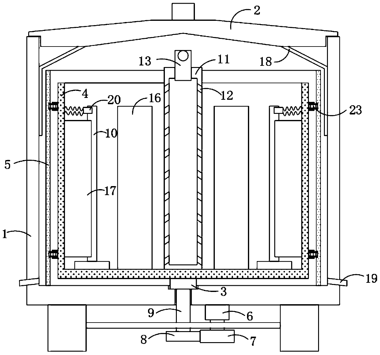
[0003] However, the existing drying efficiency is low, and a large amount of packages are piled up in the drying room for drying, but this drying method has the following disadvantages: 1. Due to the messy and disorderly stacking, the yarn in the drying room The packages are not dried evenly, and the drying effect is different; 2. In addition, when the packages are placed in the drying room for drying, there is often no structure for collecting and discharging water vapor and water droplets in the drying room , a large amount of water vapor generated during the drying process will move upwards, and finally form water droplets to condense on the top surface of the drying chamber, and the water droplets remaining on the top surface will often fall on the cheese again, affecting the drying effect

Method used

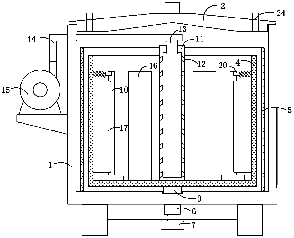
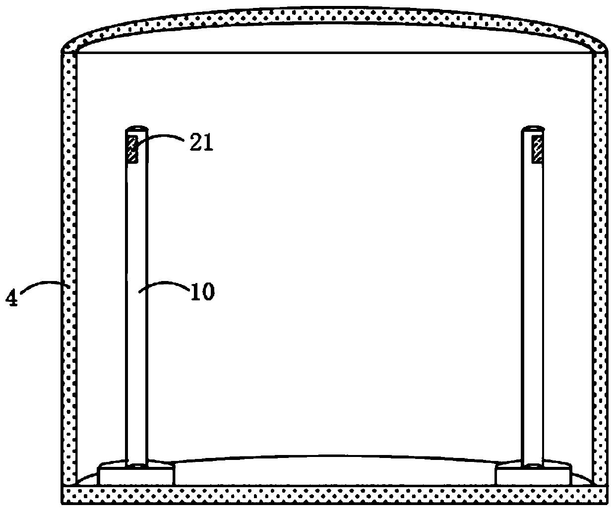

Image

  • Special spinning and drying device for cotton yarns
  • Special spinning and drying device for cotton yarns
  • Special spinning and drying device for cotton yarns

Examples


Embodiment Construction

[0028] The following will clearly and completely describe the technical solutions in the embodiments of the present invention with reference to the accompanying drawings in the embodiments of the present invention. Obviously, the described embodiments are only some, not all, embodiments of the present invention.

[0029] In describing the present invention, it should be understood that the terms "upper", "lower", "front", "rear", "left", "right", "top", "bottom", "inner", " The orientation or positional relationship indicated by "outside", etc. is based on the orientation or positional relationship shown in the drawings, and is only for the convenience of describing the present invention and simplifying the description, rather than indicating or implying that the referred device or element must have a specific orientation, so as to Specific orientation configurations and operations, therefore, are not to be construed as limitations on the invention.

[0030] refer to Figure ...


PUM


Abstract

The invention discloses a special spinning and drying device for cotton yarns. The special spinning and drying device for the cotton yarns comprises an outer barrel and an inner barrel rotatably connected into the outer barrel through a rotary shaft, wherein a cover plate is arranged at the upper end of the outer barrel in a sealing way; the rotary shaft is rotatably connected to the inner bottompart of the outer barrel; a drive mechanism for driving the rotary shaft is arranged at the lower end of the outer barrel; an annular heat-insulation plate is fixedly arranged on the inner bottom partof the outer barrel in a sleeving way and is arranged on the outer side of the inner barrel in a sleeving way; an air guiding cylinder is fixedly connected to the middle of the inner bottom part of the inner barrel; and the upper end of the air guiding cylinder extends to the outer side of the annular heat-insulation plate. The special spinning and drying device for the cotton yarns provided by the invention is compact in structure; the cotton yarn can be conveniently arranged on a sleeve rod in a sleeving way; through the cooperative use of the air guiding cylinder, a first flow guiding plate and a second flow guiding plate, the drying efficiency and the quality of the cotton yarns are improved; and meanwhile, in the drying process, water vapor can be favorably collected, guided to flowand discharged, so that the occurrence of the phenomenon that the drying quality is influenced due to excessive moisture remained in the drying device is avoided.

Description

technical field [0001] The invention relates to the technical field of drying, in particular to a special textile drying device for cheese. Background technique [0002] Package yarn is the output product of the winding process of spinning mills in the textile industry. It is the bobbin that falls from the spinning frame or twisting machine in the previous process. After the package yarn is processed, it must be dried. [0003] However, the existing drying efficiency is low, and a large amount of packages are piled up in the drying room for drying, but this drying method has the following disadvantages: 1. Due to the messy and disorderly stacking, the yarn in the drying room The packages are not dried evenly, and the drying effect is different; 2. In addition, when the packages are placed in the drying room for drying, there is often no structure for collecting and discharging water vapor and water droplets in the drying room , a large amount of water vapor generated during...

Claims


Application Information

Patent Timeline
Patent Type & Authority Applications(China)
IPC IPC(8): F26B11/08F26B21/00F26B25/16F26B25/00
CPCF26B11/08F26B21/001F26B25/00F26B25/16
Inventor 张晓英许炜玮温月梅
Owner 江西荣盛棉纺有限公司
Learn More