Auto-cascade refrigeration system, drying device with same and operation method
A technology of refrigeration system and operation method, which is applied in the direction of dry gas arrangement, dryer for static materials, refrigerator, etc., and can solve problems such as difficult adjustment, large initial investment, and complex structure
- Summary
- Abstract
- Description
- Claims
- Application Information
AI Technical Summary
Problems solved by technology
Method used
Image
Examples
Embodiment 1
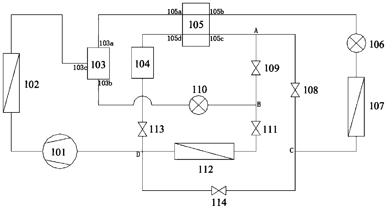
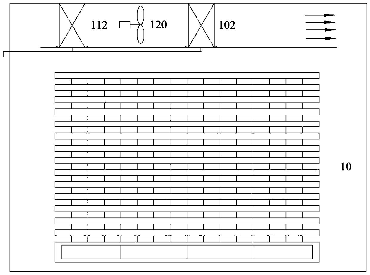
[0042] Such as Figure 1-2 As shown, a self-cascading refrigeration system has a binary non-azeotropic refrigerant, the difference between the boiling point temperature of the two components is more than 10°C, the critical temperature of the high boiling point refrigerant is between 80°C and 200°C, and the low boiling point refrigerant The critical temperature of the agent is between 30°C and 120°C. Specifically, binary zeotropic refrigerants composed of R32, R134a, R290, R1234ze(E), R1234ze(Z), R1233zd(E), R245fa, etc. can be selected.
[0043] Such as figure 1 As shown, the self-cascading refrigeration system has a compressor 101, a condenser 102, a separation device 103, a first throttling device 110, an evaporative condenser 105, a liquid storage device 104, a second throttling device 106, and a low-temperature evaporator 107 , high temperature evaporator 112;
[0044] Wherein the exhaust outlet of the compressor is connected with the inlet of the condenser 102, and the...
Embodiment 2
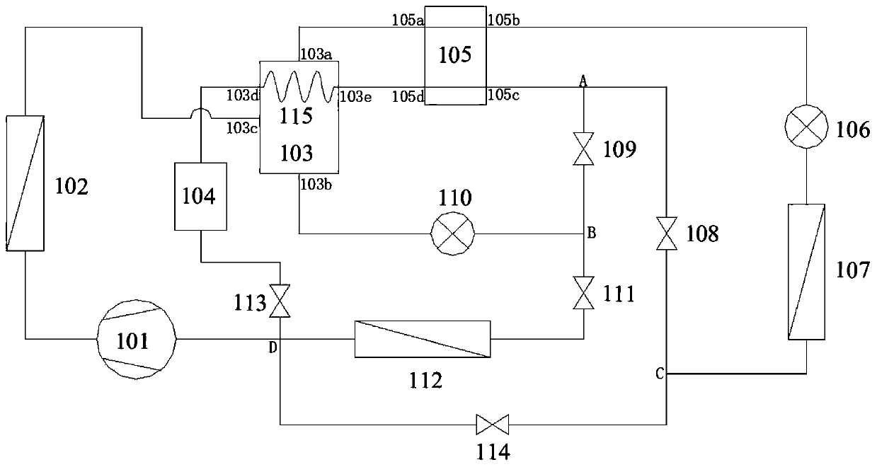
[0051] Such as image 3 As shown, on the basis of Example 1, a subcooler 115 is added in the separation device 103, and the subcooler is arranged between the evaporation side outlet 105d of the evaporative condenser 105 and the inlet of the liquid storage device 104. On the flow channel and located in the upper space inside the separation device 103, it is used to condense the high boiling point components in the refrigerant gas rich in low boiling point components.
[0052] Others are the same as embodiment 1.
Embodiment 3
[0054] Such as Figure 4As shown, on the basis of Embodiment 1, a four-way reversing valve 106 is added, and a sixth control valve 117 is added between the separation device 103 and the condensing side inlet (105a) of the evaporative condenser 105; the four-way reversing valve 106 has Four ports, that is, the first port 106a, the second port 106b, the third port 106c, and the fourth port 106d, wherein the first port 106a is connected to the suction inlet of the compressor, and the second port 106b is connected to the inlet of the high-temperature evaporator 112, The third port 106c is connected to the discharge port of the compressor, and the fourth port 106d is connected to the inlet of the condenser 102 .
[0055] Others are the same as embodiment 1.
[0056] Therefore, the refrigerating system of this embodiment can make the drying device realize the forward rotation and reverse rotation of the fan 120 through the forward cycle and the reverse cycle to perform dehumidifica...
PUM
 Abstract
Description
Claims
Application Information
 - R&D
- Intellectual Property
- Life Sciences
- Materials
- Tech Scout
- Unparalleled Data Quality
- Higher Quality Content
- 60% Fewer Hallucinations
Browse by: Latest US Patents, China's latest patents, Technical Efficacy Thesaurus, Application Domain, Technology Topic, Popular Technical Reports.
© 2025 PatSnap. All rights reserved.Legal|Privacy policy|Modern Slavery Act Transparency Statement|Sitemap|About US| Contact US: help@patsnap.com


