Combined transmission conversion mechanism

A technology of combined transmission and combined gear, applied in the direction of transmission, gear transmission, mechanical equipment, etc., can solve the problems of bloated mechanism, complex structure, inability to realize power cut off and combination, deceleration or speed increase, etc. The effect of low cost and simple maintenance

Active Publication Date: 2019-09-06
XIAN TECHNOLOGICAL UNIV
View PDF10 Cites 0 Cited by
  • Summary
  • Abstract
  • Description
  • Claims
  • Application Information

AI Technical Summary

Problems solved by technology

[0002] With the rapid development of my country's economy, more profound changes have taken place in industries such as automobiles, petroleum, motorcycles, and aerospace. Mechanical transmission, assembly lines, and food packaging all require combined transmission conversion mechanisms. The existing combined transmission conversion mechanisms are bloated. , The structure is complicated, and only one-way flow of power can be realized, and two-way flow of power cannot be realized; and the existing combined transmission conversion mechanism cannot realize the power cutting and combination, deceleration or speed-up of three axes on a straight line

Method used


Image

  • Combined transmission conversion mechanism
  • Combined transmission conversion mechanism
  • Combined transmission conversion mechanism

Examples


Embodiment Construction

[0028] In order to make the object, technical solution and advantages of the present invention clearer, the present invention will be further described in detail below in conjunction with the accompanying drawings and embodiments. It should be understood that the specific embodiments described here are only used to explain the present invention, not to limit the present invention.

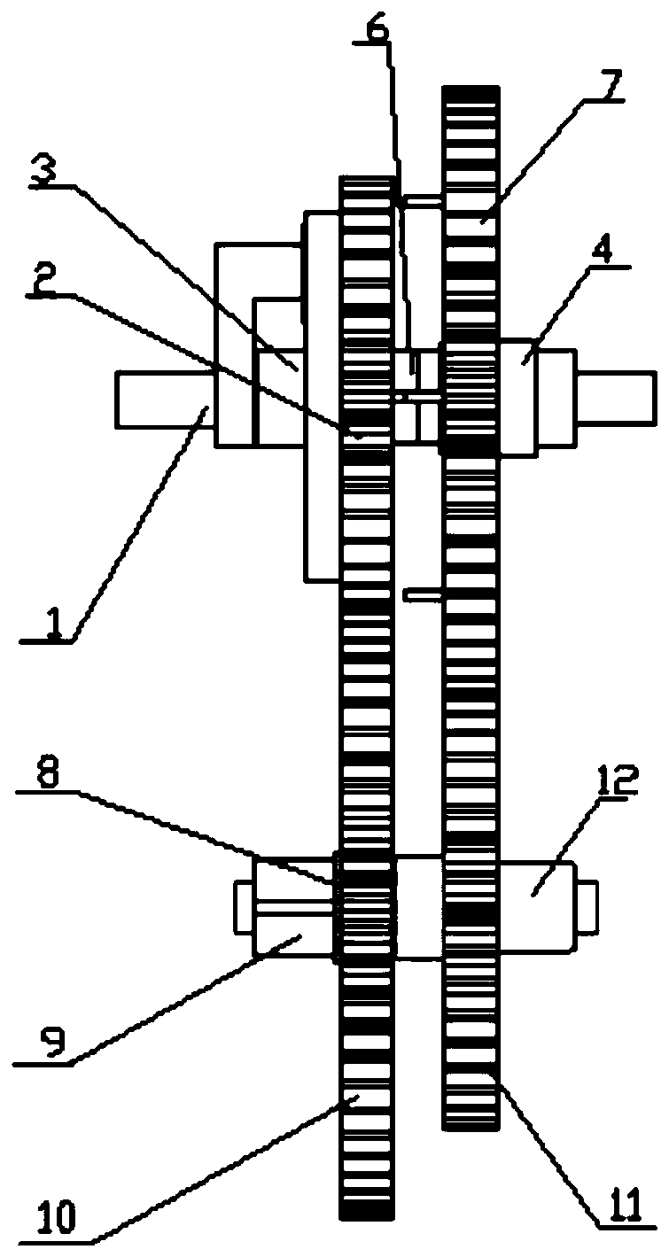
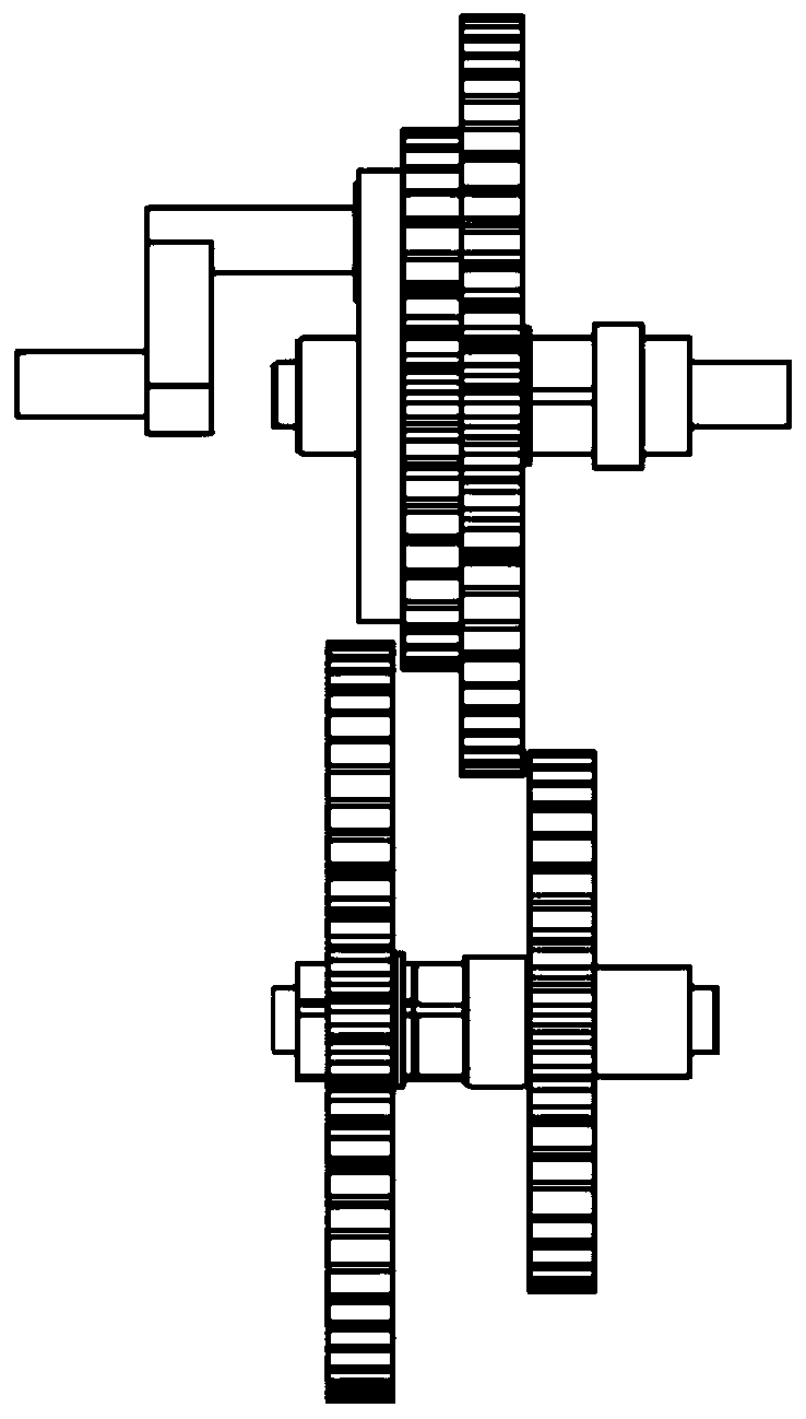
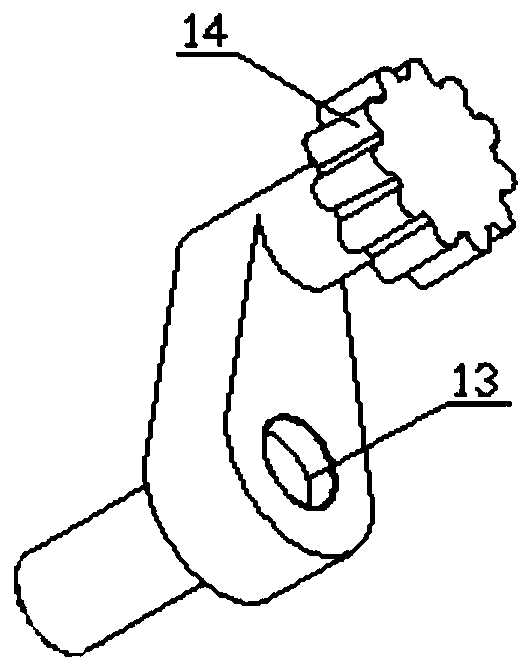
[0029] This embodiment provides a combined transmission conversion mechanism (see figure 1 with figure 2 ), including epicycloid gear crankshaft 1, combined gear 1, shaft 1 3, shaft 2 4, angular contact bearing 5, spline sleeve 6, combined gear 2 7, intermediate shaft 9, cylindrical gear 10, cylindrical gear Two 11, cylindrical sleeve 12, epicycloid gear 14 and hypocycloid ring gear 15;

[0030] The above-mentioned epicycloid gear crankshaft 1, combined gear one 2, shaft one 3, and shaft two 4 cooperating with the epicycloid gear are on a straight line (see Figure 9-Figure 11 ).

[0031] The ...


PUM


Abstract

The invention relates to a combined transmission conversion mechanism. The mechanism comprises an epicycloidal gear crankshaft. A shaft hole matched with the outer race of an angular contact ball bearing is formed in the epicycloidal gear crankshaft. The angular contact ball bearing is matched with an A segment of a shaft I. A hypocycloidal gear ring is arranged on the left end surface of a combined gear I. An epicycloidal gear is engaged with the hypocycloidal gear ring. The shaft I is connected with a shaft II through the angular contact ball bearing. A C segment on the shaft I is matched with a spline socket. A spline groove matched with a combined gear II is formed in an A segment of the shaft II. The combined gear II is bonded to the combined gear I by sliding on the spline groove ofthe shaft II and the spline socket, and disconnection and connection of the shaft I and the shaft II are achieved; and a spline groove and a retainer ring groove are formed in an A segment of an intermediate shaft, a key groove matched with a cylindrical gear II is formed in a B segment of the intermediate shaft, and by changing the engagement states of the combined gears and cylindrical gears, the bonding state between the combined gears and the power input direction, acceleration or deceleration transmission conversion from first-level to third-level or from third-level to first-level is achieved.

Description

technical field [0001] The invention relates to the technical field of mechanical transmission, in particular to a combined transmission conversion mechanism, which is suitable for cutting and combining, decelerating and speeding up the power of three shafts on a straight line. Background technique [0002] With the rapid development of my country's economy, more profound changes have taken place in industries such as automobiles, petroleum, motorcycles, and aerospace. Mechanical transmission, assembly lines, and food packaging all require combined transmission conversion mechanisms. The existing combined transmission conversion mechanisms are bloated. , complex structure, can only realize the unidirectional flow of power, can not realize the two-way flow of power; and the existing combined transmission transformation mechanism can not realize the power cutting and combining, deceleration or speed-up of three axes on a straight line. Contents of the invention [0003] In vi...

Claims


Application Information

Patent Timeline
Patent Type & Authority Applications(China)
IPC IPC(8): F16H1/20
CPCF16H1/206
Inventor 贾建军孙成白攀郝艺珍张泽
Owner XIAN TECHNOLOGICAL UNIV
Why Eureka
Try Eureka