Structure and control method of shielded airtight door
A technology for sealing doors and elastic seals, applied in sealing devices, windows/doors, building components, etc., can solve the problems of heavy and difficult sealing doors, manual opening and closing, and poor shielding and sealing effect, so as to improve the working environment of personnel , Good shielding and sealing effect, the effect of reducing work intensity
- Summary
- Abstract
- Description
- Claims
- Application Information
AI Technical Summary
Problems solved by technology
Method used
Image
Examples
Embodiment 1
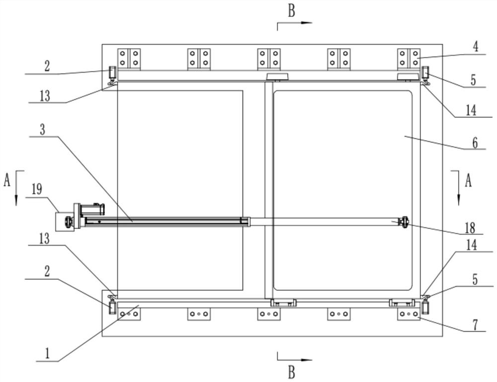
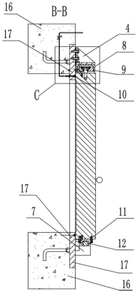
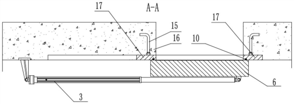
[0039] Such as Figure 1 to Figure 4 As shown, a kind of shielding and airtight door structure in this embodiment is arranged in the entrance and exit channel of the factory building or workshop that requires shielding and sealing in the nuclear industry, and mainly realizes the shielding and sealing function. The working state of the airtight door is usually a closed state, and only needs to be opened When it is opened, its structure specifically includes an electric push rod 3, a door panel 6, an upper guide rail 8, a lower guide rail 1, an opening travel switch 2 and a closing travel switch 5; wherein, the electric push rod 3 is a method that converts the rotational motion of the motor into The linear reciprocating motion of the push rod is an electric drive device. The electric push rod 3 has a motor and a telescopic push rod 18. One end of the electric push rod 3 is provided with a motor and is fixed on the wall 16 through a bolt connection. One end of the rod 18 is fixed...
Embodiment 2
[0042] A screened airtight door structure in this embodiment includes all the technical features in Embodiment 1, in addition, such as figure 1 , figure 2 and Figure 4 Shown, also comprise a plurality of conical rollers 9, a plurality of conical rollers 9 are all rotatably connected to the upper end edge of the door panel 6, the rotating shafts of a plurality of conical rollers 9 all extend along the vertical direction of the door panel 6, in the upper guide rail 8 A strip-shaped groove is provided, and a plurality of tapered rollers 9 are arranged in the strip-shaped groove and are rollingly connected with the upper guide rail 8, wherein the shape of the tapered rollers 9 is conical, and the smaller end is set upwards. The cross-sectional shape of the elongated groove provided on the upper guide rail 8 is a trapezoid with a small upper part and a larger lower part. The tapered roller 9 rolls on the elongated groove. This structure runs smoothly and reliably, and has a long...
Embodiment 3
[0047] Such as Figure 1 to Figure 4 As shown, a shielded airtight door structure in this embodiment includes all the technical features in Embodiment 2. In addition, it also includes a first bumper 13, and the door panel 6 is close to the vertical edge of the travel switch 2. A first bumper 13 is provided, and the first bumper 13 is arranged facing the opening travel switch 2. The first bumper 13 translates along with the door panel 6. When the door panel 6 moves to the fully open position, the first bumper 13 hits Turn on the travel switch 2, and transmit the signal to control the electric push rod 3 to stop running. For example, the travel switch 2 is opened to two up and down, and the door panel 6 is opened and put in place by contact with the first bumper 13 respectively; the second bumper is also included. 14. A second touch block 14 is arranged on the vertical edge of the door panel 6 close to the closed travel switch 5, and the second bump block 14 is arranged facing t...
PUM
 Abstract
Description
Claims
Application Information
 - R&D
- Intellectual Property
- Life Sciences
- Materials
- Tech Scout
- Unparalleled Data Quality
- Higher Quality Content
- 60% Fewer Hallucinations
Browse by: Latest US Patents, China's latest patents, Technical Efficacy Thesaurus, Application Domain, Technology Topic, Popular Technical Reports.
© 2025 PatSnap. All rights reserved.Legal|Privacy policy|Modern Slavery Act Transparency Statement|Sitemap|About US| Contact US: help@patsnap.com


