Soldering flux circulation tank

A circulation tank and flux technology, applied in welding equipment, auxiliary equipment, metal processing equipment, etc., can solve problems such as difficulty in controlling height and deterioration of flux

Pending Publication Date: 2019-09-06
罗定市嘉裕电子有限公司
View PDF5 Cites 0 Cited by
  • Summary
  • Abstract
  • Description
  • Claims
  • Application Information

AI Technical Summary

Problems solved by technology

[0003]Aiming at the above-mentioned technical problems, the present invention provides a flux circulation tank to solve the difficulty in controlling the height of the PIN pins of the existing components with flux , the problem of deterioration caused by flux exposure, the flux circulation tank can effectively prevent the flux from contacting the component body, and at the same time prevent the flux from deteriorating

Method used


Image

  • Soldering flux circulation tank
  • Soldering flux circulation tank
  • Soldering flux circulation tank

Examples


Embodiment Construction

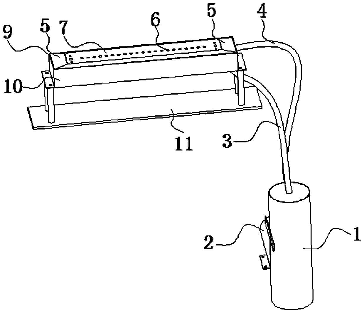
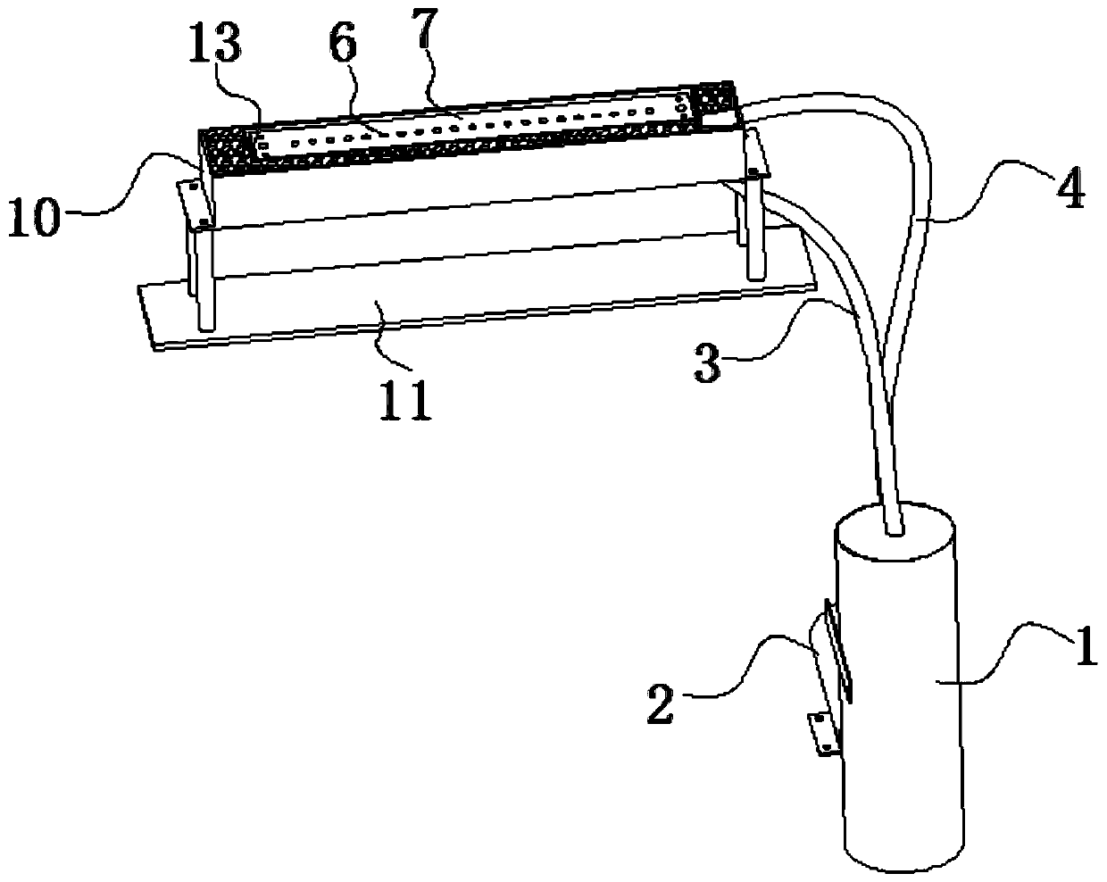
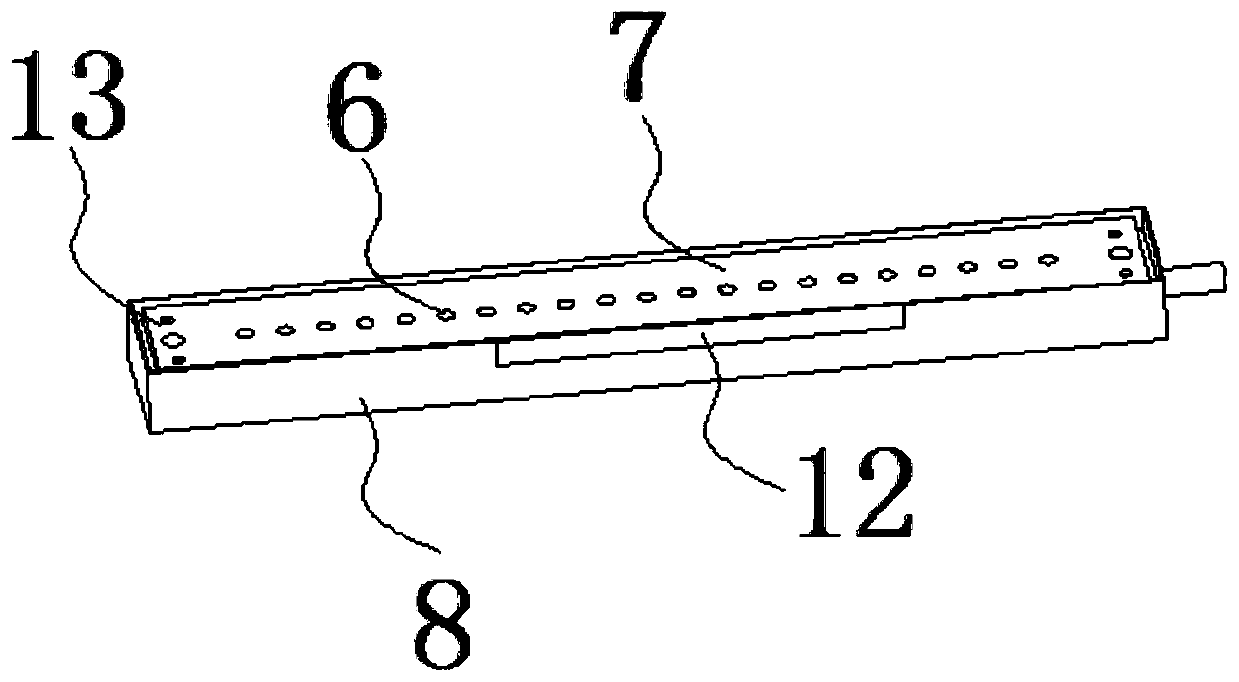
[0015] The invention discloses a flux circulation tank, which can effectively prevent the flux from contacting the component body and prevent the flux from deteriorating at the same time.

[0016] The technical solution in the present invention will be clearly and completely described below in conjunction with the accompanying drawings in the present invention. Obviously, what is described is only a part of the embodiments of the present invention, not all the embodiments. Based on the embodiments of the present invention, all other embodiments obtained by persons of ordinary skill in the art without creative efforts fall within the protection scope of the present invention.

[0017] see Figure 1-Figure 3 As shown, the present invention provides a flux circulation tank, comprising an outer cavity body 9, an inner cavity body 13, a liquid inlet pipe 4, a liquid outlet pipe 3, a liquid storage chamber 1 and a liquid inlet pump 2, and the inner cavity body 13 is located inside ...


PUM


Abstract

The invention provides a soldering flux circulation tank comprising an outer cavity, an inner cavity, a liquid inlet pipe, a liquid outlet pipe, a liquid storage cavity and a liquid inlet pump. The inner cavity is located in the outer cavity. The inner cavity comprises an inner tank body and a face plate. The face plate is located at the position of a top opening of the inner tank body. Multiple pin through holes are formed in the face plate. Silica gel is arranged in the pin through holes. Cross-shaped notches are formed in the silica gel. An overflow strip hole is formed in the side face ofthe inner tank body. The height of the overflow strip hole is smaller than that of the face plate. The outer cavity comprises an outer tank body and multiple closing plates. A top opening of the outertank body is closed by the face plate and the multiple closing plates together. The inner portion of the outer tank body and the outer portion of the inner cavity are filled with filter materials. The soldering flux circulation tank aims at solving the problems that in the existing manner that component PINs are dipped with soldering flux, it is difficult to control the height and deterioration is caused by exposure of the soldering flux.

Description

technical field [0001] The invention belongs to the technical field of soldering equipment for electronic devices, and in particular relates to a flux circulation tank. Background technique [0002] Most of the existing electronic components products need to dip a little flux on the PIN pin before soldering to improve the soldering quality. If there is less, it is easy to solder when welding). Under the existing conditions, most of the flux is manually dipped, and it is difficult to control whether to dip more or less. Although the automatic soldering machine that appears on the market can complete the automatic flux dipping, the automatic soldering machine is mainly equipped with a flux tank to store a certain height. Immerse the PIN pin of the component into the flux tank. This method is difficult to control the height of the flux on the PIN pin. It is easy to cause the flux to touch the component body and affect the function of the component. The viscosity of the flux i...

Claims


Application Information

Patent Timeline
IPC IPC(8): B23K3/08
CPCB23K3/082
Inventor 邵炳志
Owner 罗定市嘉裕电子有限公司
Why Eureka
Try Eureka