
Stirrer

The technology of agitator and agitator shaft is applied in the directions of mixer accessories, mixers with rotating mixing devices, chemical instruments and methods, etc. Experience, good cooling effect and strong practicability

Active Publication Date: 2019-09-06
ZHANJIANG NONGHAI TECHNOLOGY CO LTD
View PDF6 Cites 3 Cited by
  • Summary
  • Abstract
  • Description
  • Claims
  • Application Information

AI Technical Summary

Problems solved by technology

Because the rotating speed of the stirring knife is very high, the bearing will generate a lot of heat. If the heat is not dissipated in time, the service life of the bearing will be seriously affected. For the safety of use, the safety regulations require the existing stirrer to work continuously for three It needs to be shut down for half an hour after the cycle, which makes the agitator unable to work continuously, resulting in poor practicability of the agitator. In addition, the existing agitator cannot automatically add water to the container during the working process, and a certain amount of water needs to be added to the container in advance. , which makes it difficult to control the mixing degree of water and substances, unless the machine stops midway to add water, which is less intelligent

Method used


Image

  • Stirrer
  • Stirrer
  • Stirrer

Examples


Embodiment 1

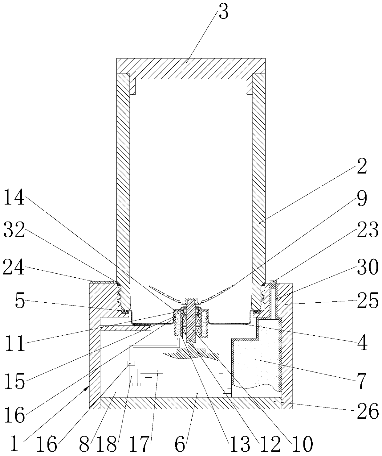
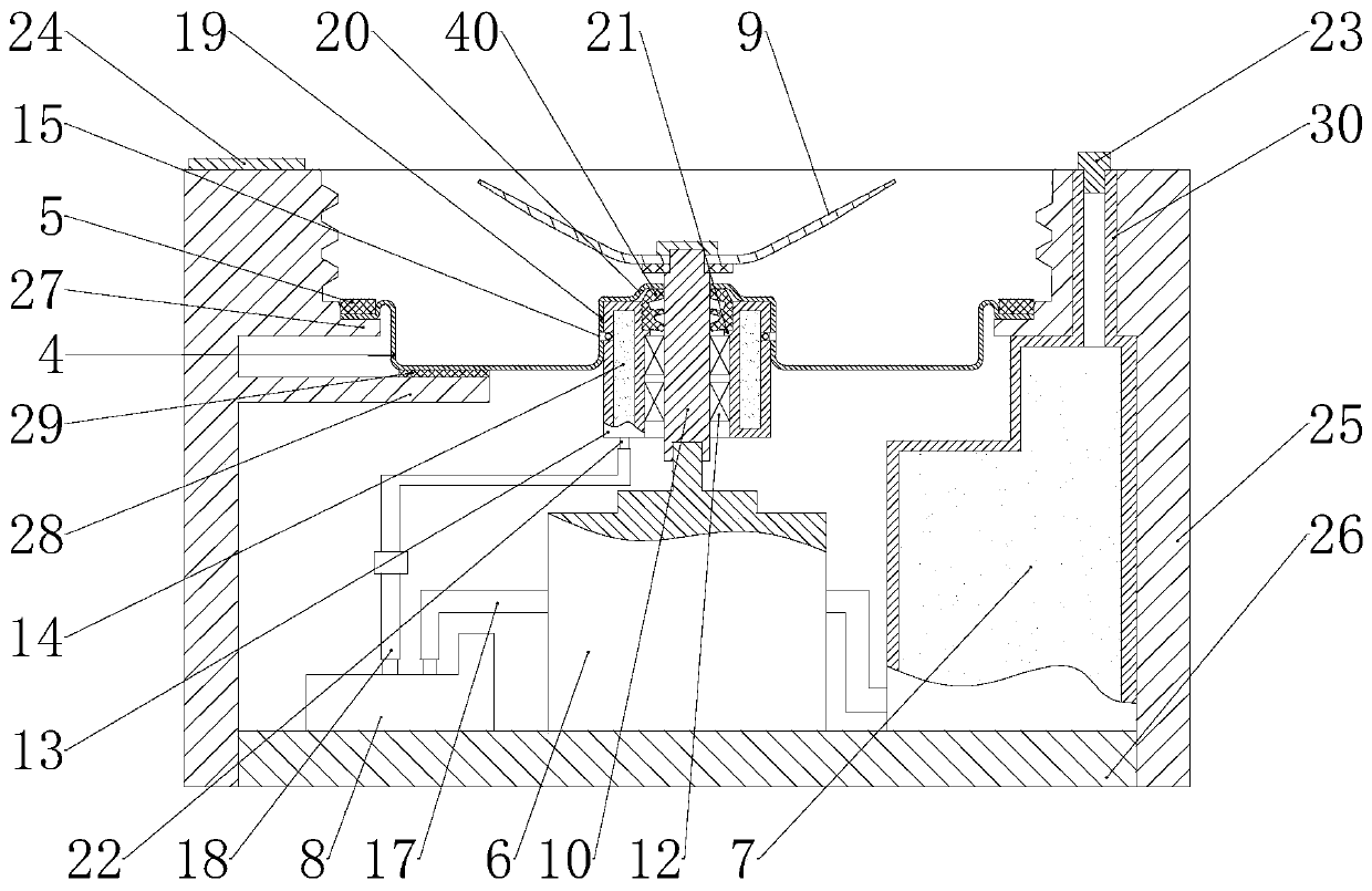
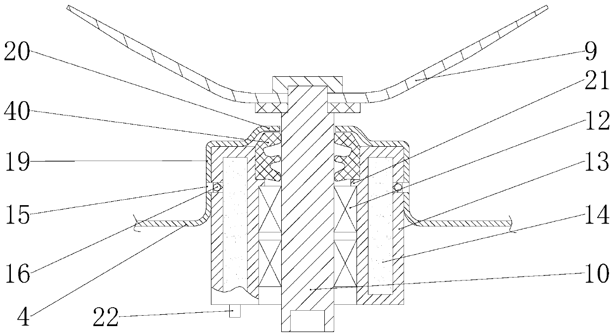
[0022] Embodiment 1: The structure of a stirrer of this embodiment is as follows Figure 1 to Figure 3 Shown includes a container base 1 and a container 2, the container 2 is screwed on the container base 1, the container 2 is a glass container, the container 2 has an upper opening and a lower opening, the upper opening is provided with a container cover 3, and the lower opening is threaded with the container base 1 Connection, the lower opening is provided with a container bottom 4, a sealing gasket 5 is provided between the lower opening and the container bottom 4, and the sealing gasket 5 is squeezed on the container bottom 4 when the lower opening is screwed on the container base 4, and the container base 1 is provided with The motor 6, the water tank 7 and the water pump 8, the top of the container bottom 4 is provided with a stirring knife 9, the stirring knife 9 is a sharp-edged knife, the stirring knife 9 is connected with a stirring shaft 10, the container bottom 4 is ...

Embodiment 2

[0025] Example 2: as Figure 4 As shown, the water tank 7 can also be detachably arranged in the container base 1, and the container base 1 is provided with a water tank cavity 31 for accommodating the water tank 7, and the water tank 7 is provided in the water tank cavity 31 in a drawable manner, so that the water injection plug 23 is not required. , the structure is simpler.

[0026] In the mixer of the present invention, a water tank and a water pump are arranged in the container base. The water pump is connected with a water suction pipe and a water inlet pipe. There is a water inlet hole connected with the annular cavity, and a one-way valve is arranged between the water inlet hole and the annular cavity, so that by controlling the opening of the water pump, even in the process of the agitator working, water can be automatically added to the container, intelligent Good, and there is a one-way valve on the water inlet pipe, and the bearing of the stirring shaft is set clo...


PUM


Abstract

The invention discloses a stirrer. The stirrer comprises a container seat and a container, the container is connected to the container seat in a threaded manner, the container is provided with an upper opening and a lower opening, the upper opening is provided with a container cover, the lower opening is in threaded connection with the container seat, the lower opening is provided with a containerbottom, a sealing gasket is arranged between the lower opening and the container bottom, a motor, a water tank and a water pump are arranged in the container, stirring blades are arranged above the container bottom, the stirring blades are connected with a stirring shaft, the center of the container bottom protrudes upwards to form a fixing seat, the stirring shaft goes through the container bottom and is connected with the motor, a bearing sleeves the stirring shaft, a heat conducting sleeve sleeves the bearing, the heat conducting sleeve is in interference fit in the fixing seat, an annularsleeve is arranged in the heat conducting sleeve, the sidewall of the fixing seat is provided with a water inlet hole, a check valve is arranged between the water inlet hole and the annular cavity, the water pump is communicated with a water suction tube and a water inlet tube, the water suction tube is communicated with the water tank, the water inlet tube is communicated with the annular cavity, and the water inlet tube is provided with a check valve. The stirrer of the invention can work continuously, and has a high practicability.

Description

technical field [0001] The invention relates to the technical field of stirring, in particular to a stirrer that can work continuously. Background technique [0002] The agitator generally includes a container base and a container. The bottom of the container is provided with a stirring blade, and the stirring blade is provided with a stirring shaft. The stirring shaft is installed at the bottom of the container through a bearing. A motor is installed in the container base. The power switch on the container base, the motor in the container base rotates to drive the stirring shaft to rotate, and then drives the stirring knife at the bottom of the container to rotate, cutting and stirring the substances in the container. Because the rotating speed of the stirring blade is extremely high, the bearing will generate a lot of heat. If the heat is not dissipated in time, the service life of the bearing will be seriously affected. In order to use safety, the safety regulations requi...

Claims


Application Information

Patent Timeline
Patent Type & Authority Applications(China)
IPC IPC(8): B01F7/18B01F15/00B01F15/06
CPCB01F27/21B01F35/322B01F27/90B01F2035/98B01F35/92
Inventor 沈婷婷其他发明人请求不公开姓名
Owner ZHANJIANG NONGHAI TECHNOLOGY CO LTD
Learn More