
Portable electrical impedance detection system

A detection system, electrical impedance technology, applied in diagnostic recording/measurement, medical science, medical automated diagnosis, etc., can solve the problem of unfavorable image and report storage, the development of medical intelligence, the inability to obtain the impedance spectrum of biological tissue cells, and the inability to impedance Spectrum or tomographic image analysis and other issues, to achieve the effect of intelligent diagnosis, enhanced convenience and reliability, and easy development and integration

Inactive Publication Date: 2019-09-06
NANJING UNIV OF AERONAUTICS & ASTRONAUTICS
View PDF4 Cites 7 Cited by
  • Summary
  • Abstract
  • Description
  • Claims
  • Application Information

AI Technical Summary

Problems solved by technology

[0006] Most of the electrical impedance measurement equipment currently on the market needs to use a PC as the upper computer, which is bulky, complicated to operate, redundant in function, low in automation, not portable, and limited to use in laboratories and other occasions.
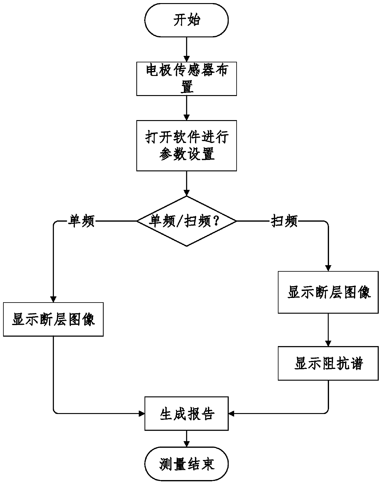
Most electrical impedance measurement equipment can only image at a single frequency, and cannot realize the frequency sweep function, so it is impossible to obtain the impedance spectrum of biological tissue cells, and the impedance spectrum also carries a large amount of cell information; secondly, it is impossible for untrained personnel to measure the impedance Spectrum or tomographic images are analyzed, and preliminary decisions cannot be made automatically on the detection results; finally, almost no electrical impedance measurement equipment has the function of Internet cloud connection, which is not conducive to the storage of generated images and reports and the development of medical intelligence

Method used


Image

  • Portable electrical impedance detection system
  • Portable electrical impedance detection system
  • Portable electrical impedance detection system

Examples


Embodiment Construction

[0024] The present invention will be further described below in conjunction with the accompanying drawings.

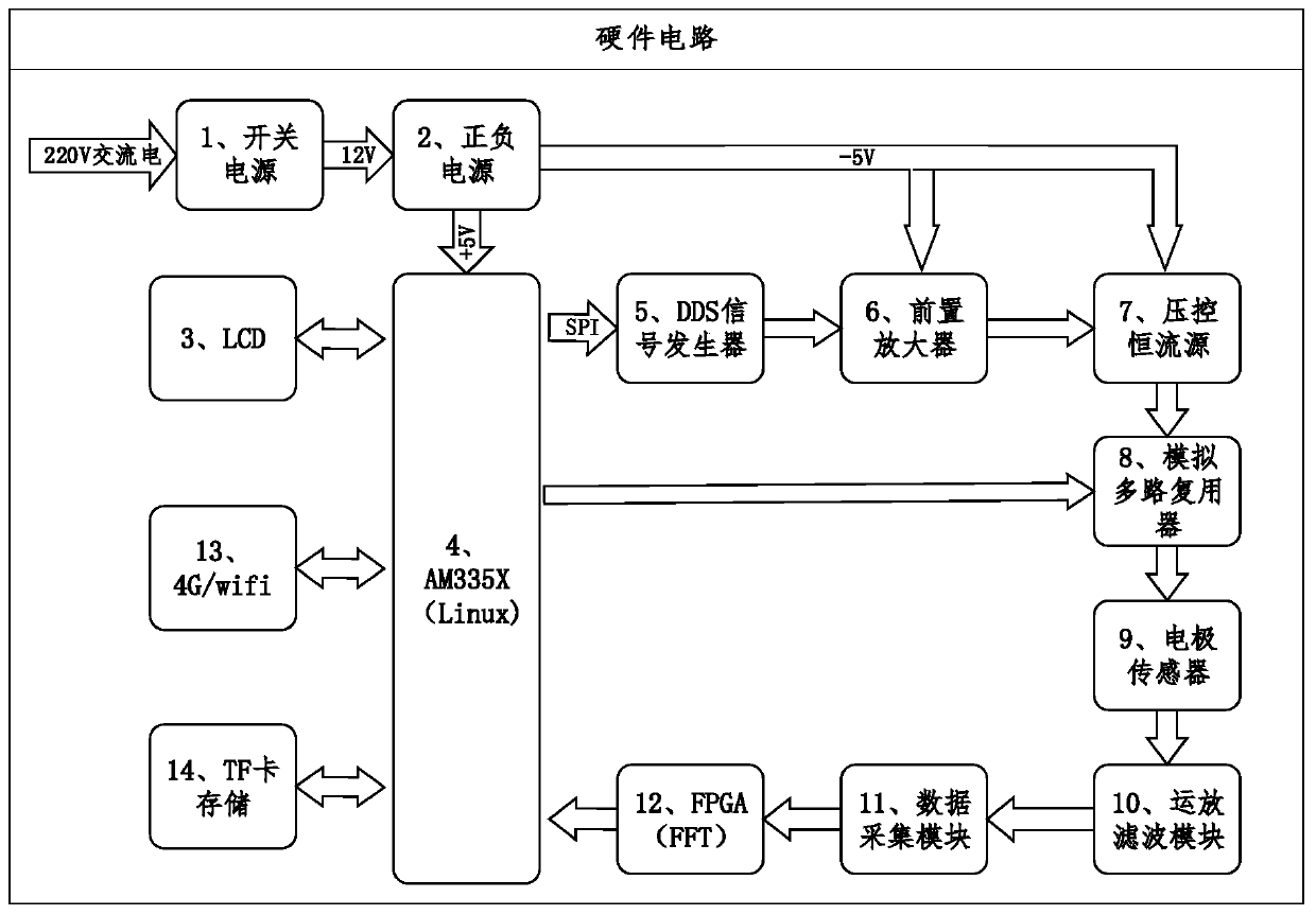
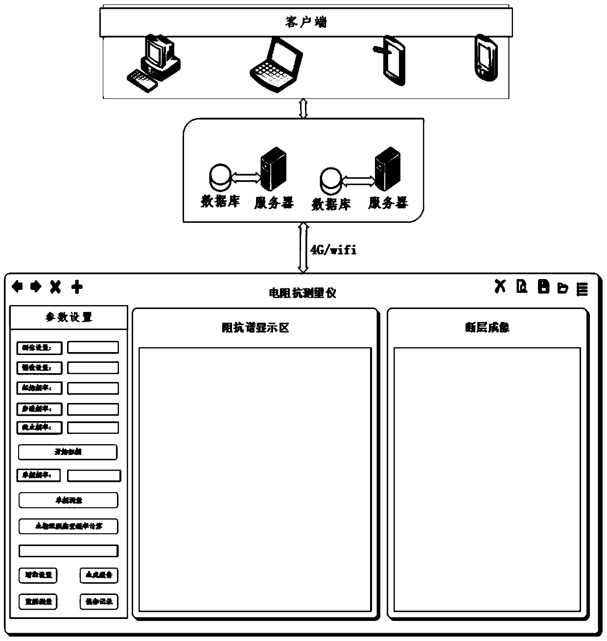
[0025] The portable electrical impedance detection system of the present invention comprises sequentially connected power supply circuit, LCD3, embedded Linux system 4, wireless communication module, DDS signal generator 5, preamplifier 6, voltage-controlled constant current source 7, analog multiplexer 8. Electrode sensor 9, operational amplifier filter module 10, data acquisition module 11, 4G / wifi module 13, TF card storage 14, cloud server and Android APP. The power circuit includes switching power supply and positive and negative power supply.

[0026] ARM embedded as the main control, runs the Linux embedded operating system, realizes the interaction of the human-machine interface in the user layer, drives the relevant hardware at the kernel layer, and allocates pin resources to connect with peripherals at the hardware layer.

[0027] The user layer mainly sets ...


PUM


Abstract

The invention discloses a portable electrical impedance detection system which adopts an ARM embedded Linux system as main control and consists of a wireless communication module, a DDS signal generator, a preamplifier, a voltage controlled constant current source, an analog multiplexer, an operation-amplification filter module, a data acquisition circuit, an FPGA and an electrode sensor as peripheral measuring equipment; an embedded Qt environment is adopted for software development, a cloud server is built, and a networked, informationized and intelligentized biological electrical impedancedetection platform is realized with cooperation of a client APP. The problem of matching of bandwidth and output impedance is fully considered, and high-quality imaging, high-accuracy decision making,easy carrying and consulting are achieved. The electrical impedance sweep frequency measurement embedded system has simple structure, meets the requirements of frequency range and accuracy, greatly reduces the cost and size, designs an overall scheme based on the Internet, and makes up for the deficiency that general portable impedance measurement equipment can only be used for measuring locally.

Description

[0001] Technical field: [0002] The invention relates to a portable electrical impedance detection system, in particular to an internet-based portable biological tissue electrical impedance sweep measurement embedded system. [0003] Background technique: [0004] Electrical impedance tomography (EIT) is a process tomography developed from electrical capacitance tomography (ECT) and electrical resistance tomography (ERT), and has shifted from the industrial field to the biomedical field in recent years. This measurement method distributes electrode sensors around biological tissues, injects safe sinusoidal excitation signals through sweeping frequency, acquires waveforms passing through biological tissues through high-speed signal acquisition devices, and analyzes and processes them. The different electrical conductivity characteristics in different states can reconstruct the electrical conductivity distribution image inside the tissue, so as to determine whether there is a le...

Claims


Application Information

Patent Timeline
Patent Type & Authority Applications(China)
IPC IPC(8): A61B5/053G16H50/20
CPCA61B5/0536A61B5/7475G16H50/20
Inventor 刘凯王松陈怀瑾姚佳烽王欢
Owner NANJING UNIV OF AERONAUTICS & ASTRONAUTICS
Learn More