Pressure relief structure and electric steamer with same

A technology of pressure relief structure and electric steamer, which is applied in the field of electric steamer, can solve the problems of complex structure, many spare parts and high cost, and achieve the effect of simplifying the pressure relief structure, maintaining integrity and reducing the number of openings

Pending Publication Date: 2019-09-06
VATTI CORP LTD
View PDF0 Cites 4 Cited by
  • Summary
  • Abstract
  • Description
  • Claims
  • Application Information

AI Technical Summary

Problems solved by technology

[0002] At present, the pressure relief method of the high-pressure electric steamer is: the inner tank is equipped with a pressure-limiting valve assembly, which is mainly composed of a pressure-limiting weight and an exhaust pipe. Exhaust, so that the inner tank maintains a certain pressure. Since the exhaust of the pressure limiting valve is discharged from the surrounding of the pressure weight, in order to prevent the steam from flowing into the electrical components in the machine, the exhaust hood needs to form a fixed exhaust channel. The inner tank also needs to Connect the pressure relief solenoid valve so that when the user stops pressure cooking, the solenoid valve can be opened for rapid pressure relief; this pressure steam box pressure relief system has a complex structure, many spare parts, and high cost. There are also spring-type pressure-limiting solenoid valves on the market Pressure relief valve, and the spring and sealing silicone are affected by steam temperature and food grease, and the life is shorter and often shorter

Method used


Image

  • Pressure relief structure and electric steamer with same
  • Pressure relief structure and electric steamer with same
  • Pressure relief structure and electric steamer with same

Examples


Embodiment Construction

[0026] In order to make the object, technical solution and advantages of the present invention clearer, the present invention will be further described in detail below in conjunction with the accompanying drawings and embodiments. It should be understood that the specific embodiments described here are only used to explain the present invention, not to limit the present invention.

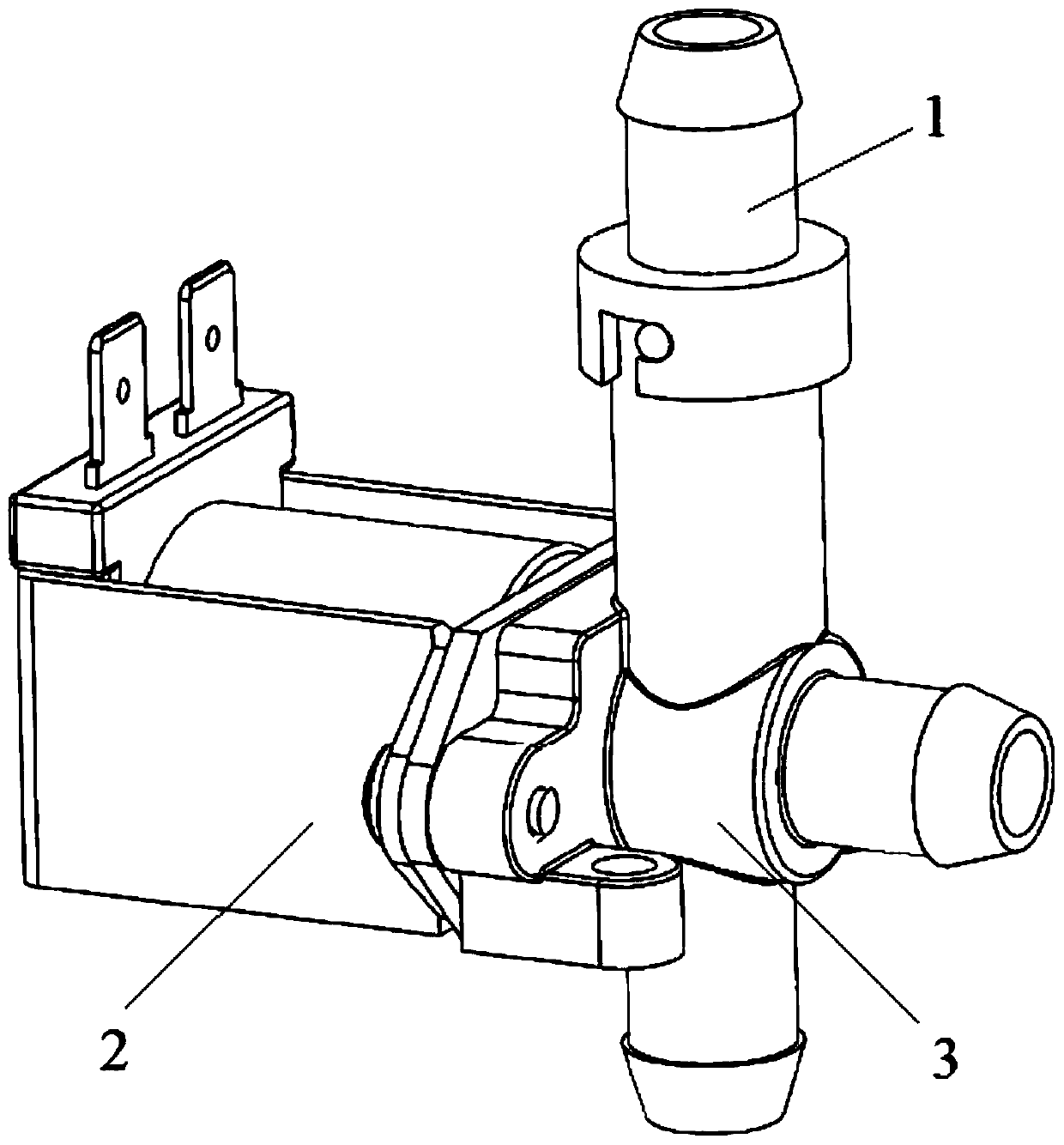
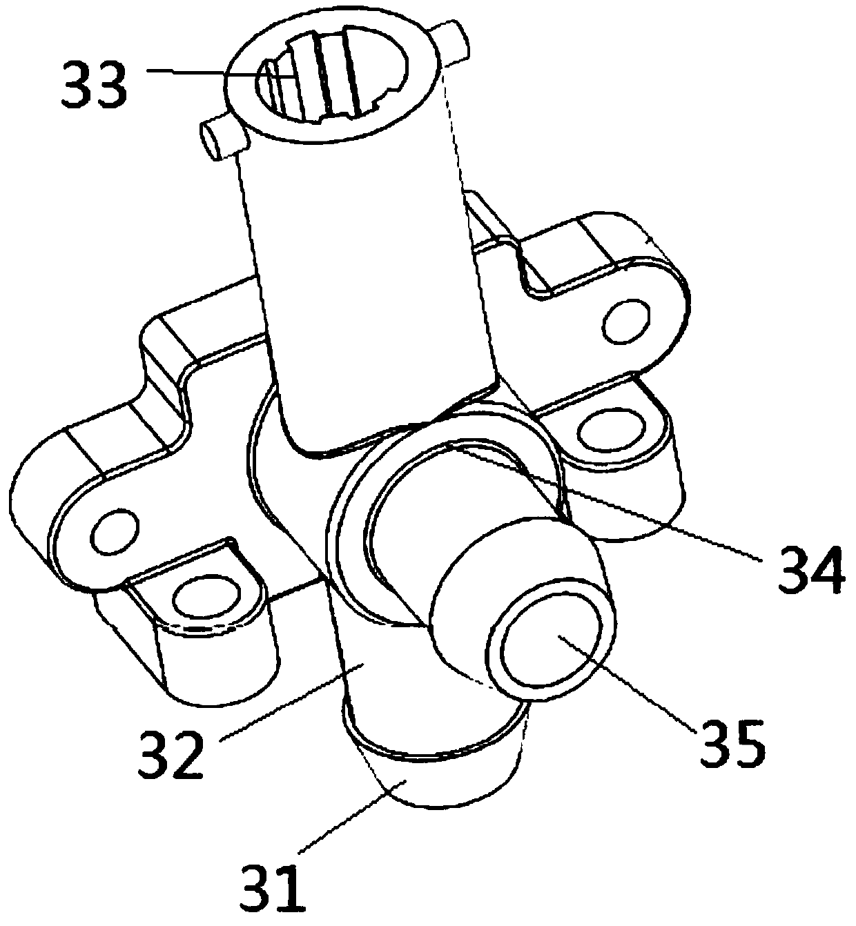
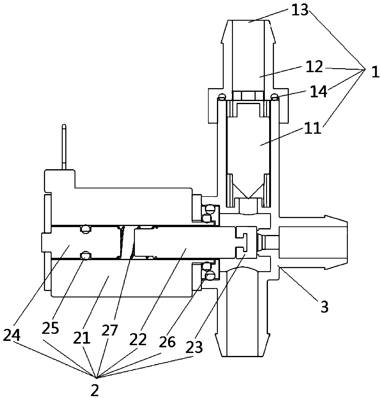
[0027] Embodiment 1 of the present invention provides a pressure relief structure, such as figure 1 As shown, it includes a gravity pressure maintaining exhaust assembly 1, a quick exhaust assembly 2 and a connecting piece 3, and the gravity maintaining pressure exhaust assembly 1 and the quick exhausting assembly 2 communicate through the connecting piece 3;

[0028] Like this, adopt above-mentioned structure, when stopping cooking needs fast pressure release, start fast exhaust assembly 2, when the pressure is big enough, under the effect of pressure, gravity maintenance pressure exhaust assembly...


PUM


Abstract

The invention discloses a pressure relief structure which comprises a gravity pressure-maintaining exhausting assembly, a rapid exhausting assembly and a connecting piece. The gravity pressure-maintaining exhausting assembly communicates with the rapid exhausting assembly through the connecting piece. In the cooking process, the gravity pressure-maintaining exhausting assembly relieves pressure inreal time to enable pressure of an inner container to be always maintained in a preset range; when cooking is stopped and rapid pressure relief is required, the rapid exhausting assembly is started to relieve pressure so that a user can safely open a door body, and at the moment, the gravity pressure-maintaining exhausting assembly continues to relieve pressure or is turned off according to pressure of the inner container; in addition, the gravity pressure-maintaining exhausting assembly and the rapid exhausting assembly are structurally combined through the connecting piece, so that the pressure relief structure is simplified.

Description

technical field [0001] The invention belongs to the technical field of kitchen appliances, and in particular relates to a pressure relief structure and an electric steamer using the same. Background technique [0002] At present, the pressure relief method of the high-pressure electric steamer is: the inner tank is equipped with a pressure-limiting valve assembly, which is mainly composed of a pressure-limiting weight and an exhaust pipe. Exhaust, so that the inner tank maintains a certain pressure. Since the exhaust of the pressure limiting valve is discharged from the surroundings of the pressure weight, in order to prevent the steam from flowing into the electrical components in the machine, the exhaust hood is required to form a fixed exhaust channel. The inner tank also needs to Connect the pressure relief solenoid valve so that when the user stops pressure cooking, the solenoid valve can be opened for quick pressure relief; this pressure steamer pressure relief system ...

Claims


Application Information

Patent Timeline
Patent Type & Authority Applications(China)
IPC IPC(8): A47J27/04A47J36/38
CPCA47J27/04A47J36/38
Inventor 陈权明麦伟添潘叶江
Owner VATTI CORP LTD
Why Eureka
Try Eureka