Stator for rotating electrical machine

A technology for rotating motors and stators, which is applied in the manufacture of stator/rotor bodies, electric components, electromechanical devices, etc. It can solve the problems of reduced efficiency of rotating motors and coil reduction, so as to ensure the space factor, prevent sagging, and achieve high efficiency. Effect

Active Publication Date: 2019-09-03
TOYOTA JIDOSHA KK
View PDF4 Cites 0 Cited by
  • Summary
  • Abstract
  • Description
  • Claims
  • Application Information

AI Technical Summary

Problems solved by technology

However, in this case, since a part of the reinforcing member is arranged in the slot, the space factor of the coil may be reduced and the efficiency of the rotating electric machine may be reduced.
Especially in the case of distributed winding, due to the winding method, the effect on the reduction in efficiency of the rotating electrical machine due to the reduction in the space factor of the coil is significant compared to concentrated winding

Method used


Image

  • Stator for rotating electrical machine
  • Stator for rotating electrical machine
  • Stator for rotating electrical machine

Examples


Embodiment 1

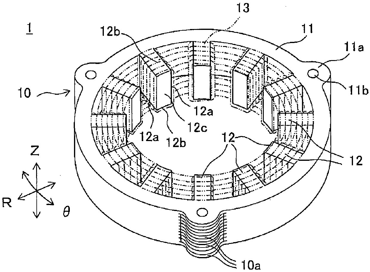
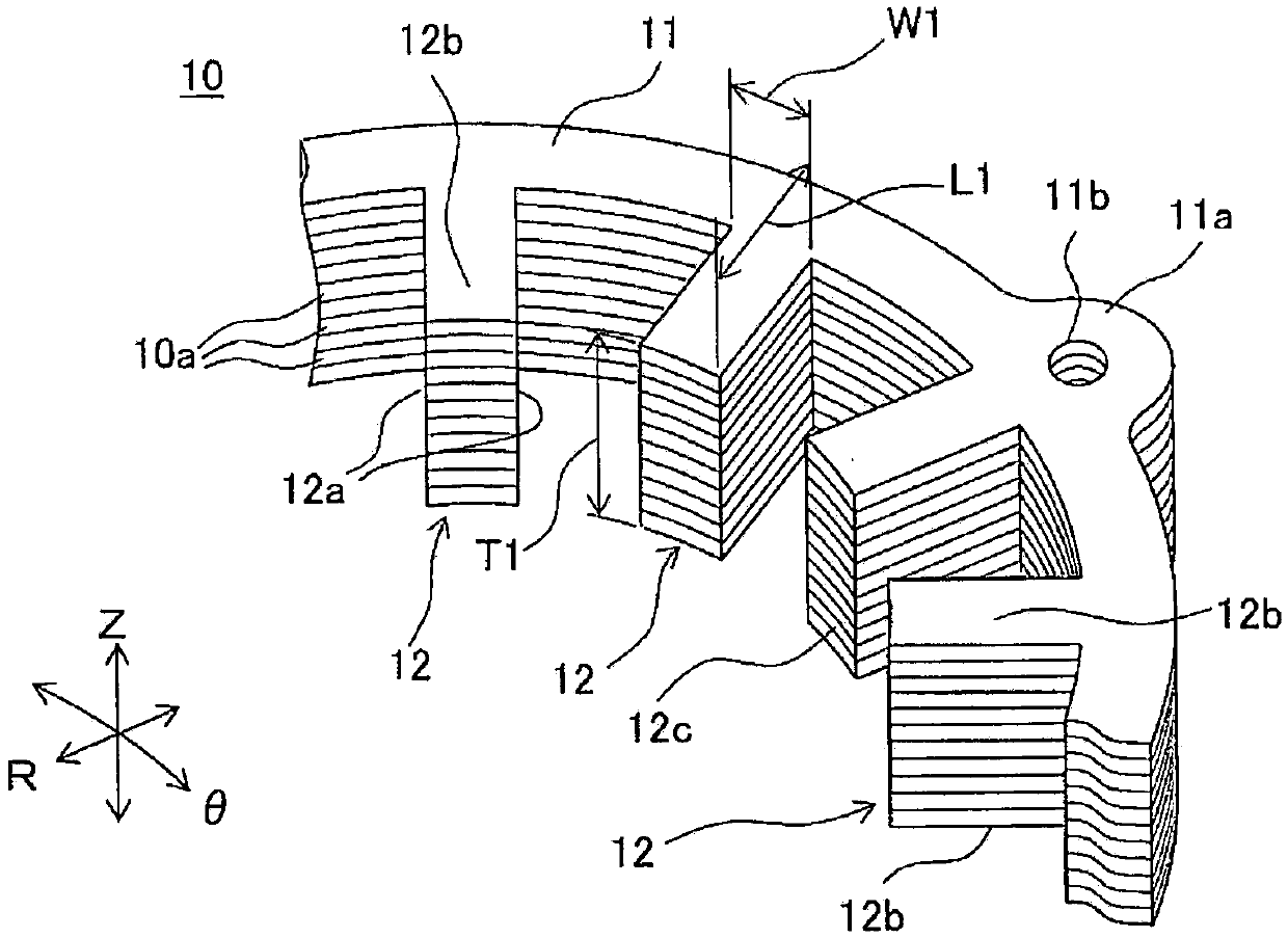
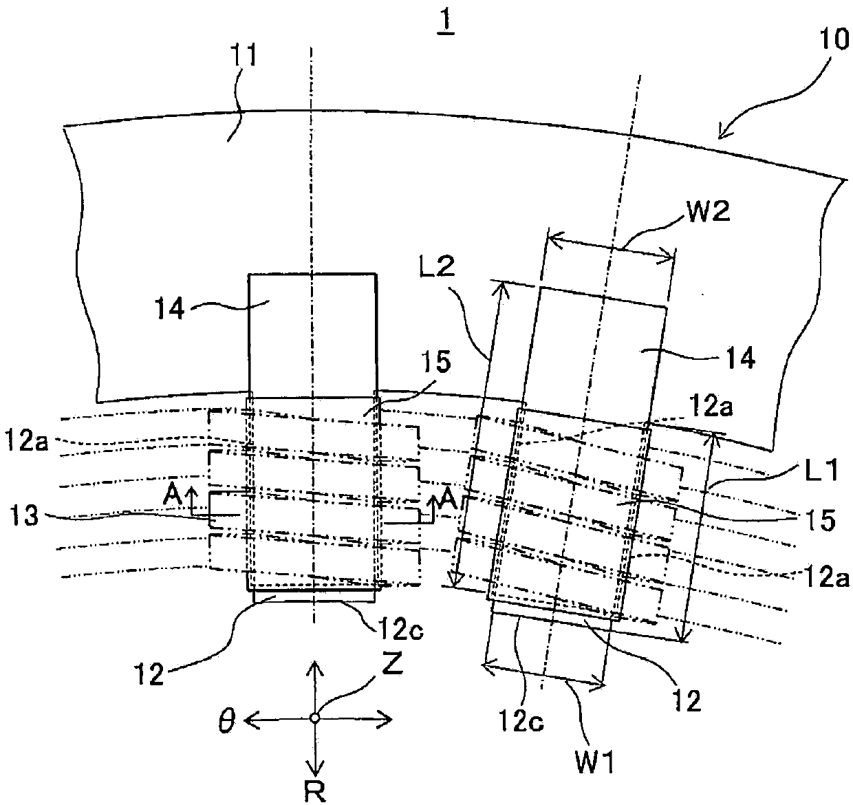
[0063] make out figure 1 A stator for a rotating electric machine is shown. Specifically, 800 foils made of a soft magnetic material (such as an Fe-based alloy with an Fe content of 80% or more produced by a liquid quenching method) with a thickness of 0.025 mm are laminated to form a laminate. A pair of reinforcing members made of an insulating material (unsaturated polyester resin) sandwich each tooth portion of the stator core as a laminated body with respect to the laminated body. In this state, a fixing member made of a tubular insulating material (polyvinyl chloride) fixes a pair of reinforcing members to each tooth portion so as to surround each tooth portion together with a pair of reinforcing members. Next, the conductive wire on which the insulating coating was formed was wound around the stator core in a distributed winding (wave winding) manner to form a coil, thereby producing a stator for a rotating electric machine.

Embodiment 2

[0071] When a model corresponding to the stator of Example 1 was produced and mounted on a motor, analysis software (JMAG-Designer) was used to analyze the loss of the motor when the rotational speed of the motor was 9000 rpm. exist Figure 11 The results are shown in . exist Figure 11 In , the loss of the motor of Example 2 is set to 1.


PUM


Abstract

Provided is a stator for rotating electrical machine that can avoid the sagging of teeth stacked at the distal ends under the self-weight. A stator core (10) is a laminate of metal foil members (10a)stacked in a direction of a rotation axis (Z) of the rotating electrical machine. Each tooth (12) has a pair of side walls (12a, 12a) facing the neighboring teeth (12, 12) in the circumferential direction (theta). The stator (1) includes a pair of insulating reinforcing members (14, 14) so as to become a bridge between the corresponding tooth and a part of the yoke and sandwich the corresponding tooth (12) from both sides in the direction of the rotation axis (Z) while exposing the pair of side walls; insulating fixing members (15), each fixing member fixing the corresponding pair of reinforcing members (14) to the corresponding tooth (12) while wrapping around the pair of reinforcing members and tooth (12); and coils (13) formed as distributed windings at the teeth (12, 12) fixed with thefixing members (15).

Description

technical field [0001] The present invention relates to a stator for a rotating electric machine used for a generator, an electric motor, etc., and particularly relates to a stator for a rotating electric machine including a coil on a stator core formed by laminating a plurality of foil materials. Background technique [0002] Conventionally, such a stator for a rotating electrical machine includes a stator and a coil wound around the stator. As such a stator for a rotating electrical machine, Patent Document 1 proposes a stator including a stator core formed by stacking core pieces (foil materials) made of a soft magnetic material in the direction of the rotation axis. A tooth portion is formed on the stator core, and a coil is formed on the stator core by winding a wire around the tooth portion by distributed winding or concentrated winding. [0003] prior art literature [0004] patent documents [0005] Patent Document 1: Japanese Patent Laid-Open No. 2015-228713 [...

Claims


Application Information

Patent Timeline
Patent Type & Authority Applications(China)
IPC IPC(8): H02K1/14H02K3/52H02K15/02
CPCH02K1/146H02K3/522H02K15/02H02K3/18H02K15/10H02K3/525
Inventor 小森健祐岁田寿充芳贺一昭
Owner TOYOTA JIDOSHA KK
Why Eureka
Try Eureka