Coil member, motor and manufacturing method for coil member

A technology for coil components and motors, which is applied in coil manufacturing, coil manufacturing, and motor generator manufacturing, etc., can solve problems such as interference with the barrel 207 and damage to the winding pressure of the coil components, so as to prevent wire breakage and damage, improve Design freedom and the effect of improving efficiency

Active Publication Date: 2008-12-10
NIDEC SANKYO CORP
View PDF1 Cites 1 Cited by
  • Summary
  • Abstract
  • Description
  • Claims
  • Application Information

AI Technical Summary

Problems solved by technology

However, when the molding resin molds 204, 204' are separated in the directions indicated by the arrows P, P', there is a problem that the protrusions 206, 206' of the molding resin molds 204, 204' interfere with the cylindrical portion 207.
In particular, for a coil component used in a small motor, since the thickness of the cylindrical portion 207 is thin, when the molding resin molds 204, 204' are separated, the protrusions 206, 206' may be interfered to cause cracks in the cylindrical portion 207. , in the worst case, there will be a problem that the coil part will be damaged because it cannot withstand the winding pressure of the winding wound on the barrel 207

Method used


Image

  • Coil member, motor and manufacturing method for coil member
  • Coil member, motor and manufacturing method for coil member
  • Coil member, motor and manufacturing method for coil member

Examples


Embodiment Construction

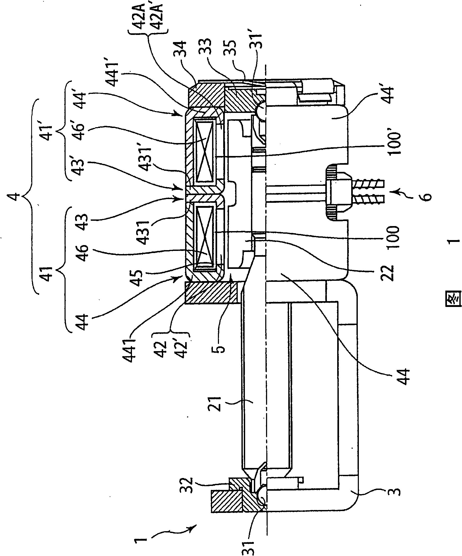
[0062] Hereinafter, a motor according to an embodiment of the present invention will be described with reference to the drawings.

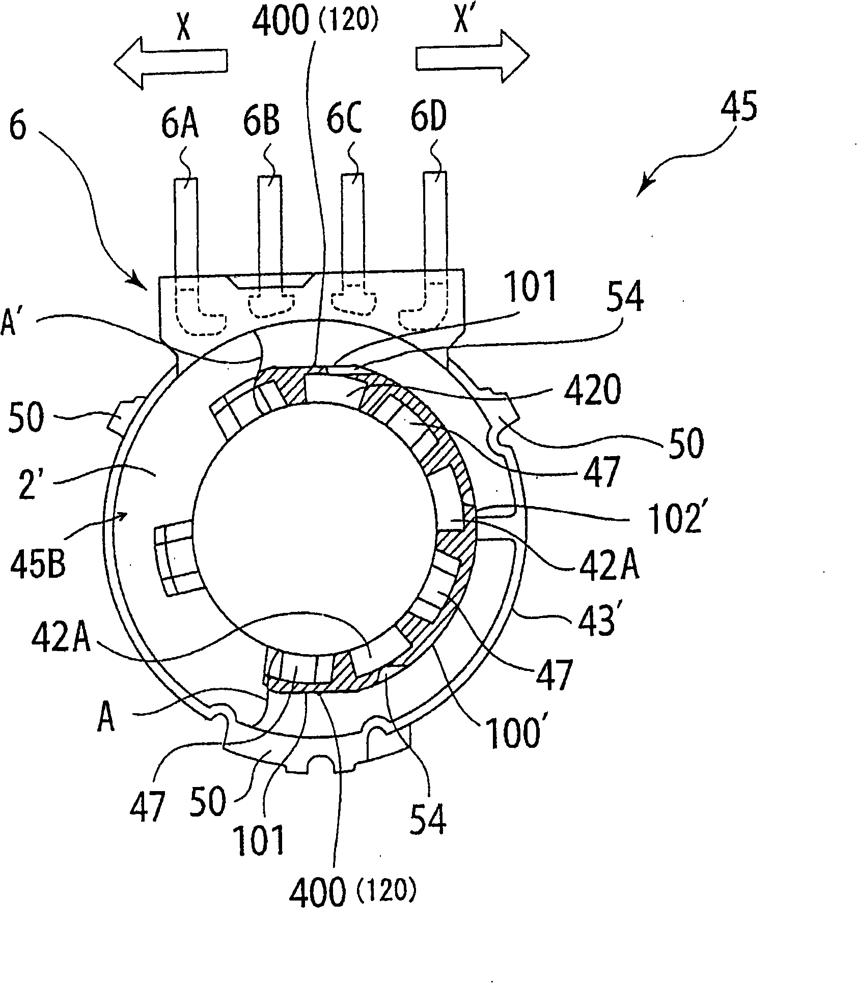
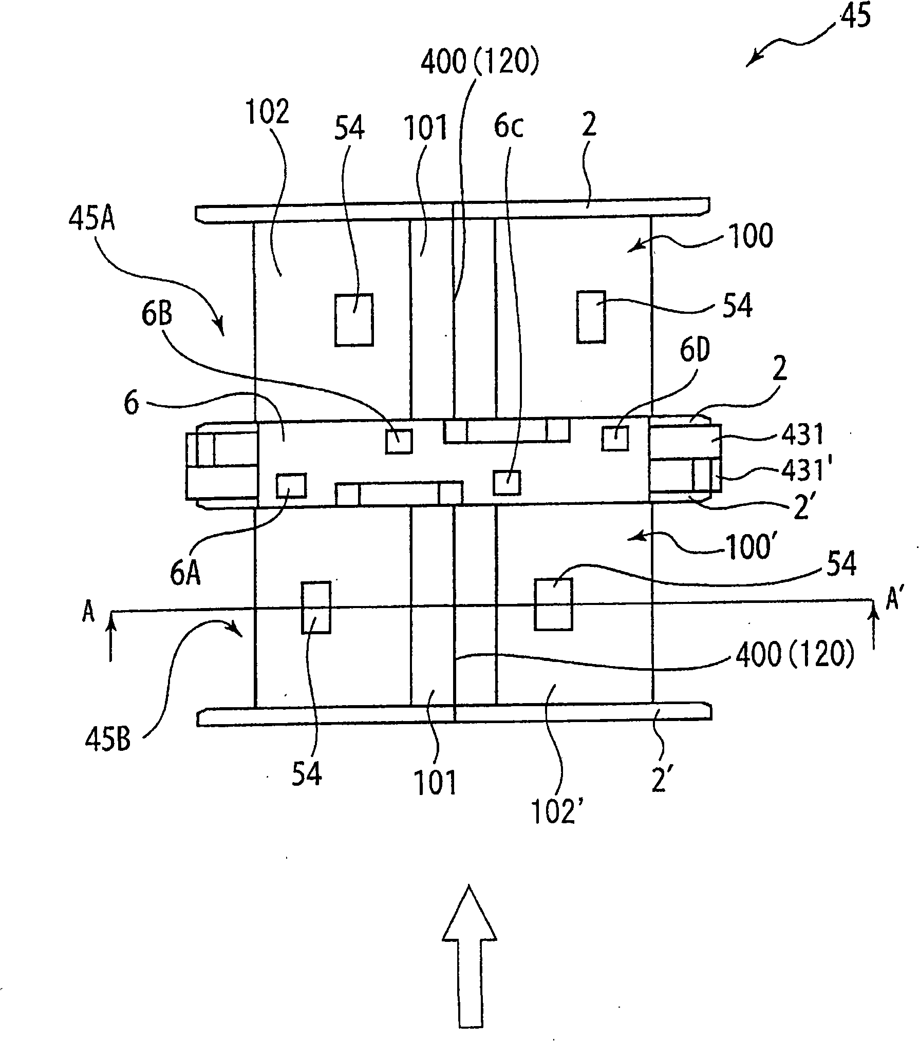
[0063] FIG. 1 is a half cross-sectional view showing an example of a motor according to an embodiment of the present invention, and an overall motor. figure 2 is to indicate that the coil part is in image 3 Partial cross-sectional view seen from the direction of the arrow with a part cut between A-A' shown. image 3 is a side view of a coil component of the motor shown in FIG. 1 . Figure 4 It is a cross-sectional view schematically showing the cylindrical portion of the coil component in a state where the slide mold is closed. Figure 5 is a cross-sectional view schematically showing a state where the inner yoke is held by the slide die and the upper die is opened. Image 6 It is a top view schematically showing the state in which the slide mold is opened. Figure 7 is enlarged Figure 4 An enlarged view of a portion around the parallel pl...


PUM


Abstract

The invention provides a coil member which can prevent winding from being broken and damaged due to fuzzy grain and can not be damaged due to the metal mould when a molding object is stripped from a metal mould even in a small-sized motor, and a motor using the coil member. In a coil member (45), a cylindrical drum part (100, 100') coiling a winding (46, 46') on the outer circumference is formed by injecting and molding two metal moulds (301, 302) moving left and right in the direction orthogonal with the axes direction of the drum part (100, 100'), the axes direction of the outer circumference has a joint part (400) of the drum part (100, 100') formed along the joint part of the two metal moulds (301, 302), the joint part (400) is formed on a parallel plane (101) formed in parallel to the separating direction of the two metal moulds (301, 302), so as not to interfere with the two metal moulds (301, 302) in the whole sliding area of the two metal moulds (301, 302) and the drum part (100) when the two metal moulds (301, 302) are separated.

Description

technical field [0001] The present invention relates to a coil component, a motor using the coil component, and a method of manufacturing the coil component. Background technique [0002] A coil device in which a coil is wound on a coil member composed of a bobbin or the like is used in a driving device such as a stepping motor. Coil components used in such coil devices are generally formed by injecting resin together with the stator core into a space formed by combining a plurality of molded resin molds that are divided structures of metal molds, and disassembling the molded resin mold after the resin is cured. formed below. For this reason, protruding burrs may be generated on the joining surface of the molding resin mold. When such a burr is formed on the cylindrical portion on which the winding is wound, the winding may be disconnected due to contact between the burr and the winding. To prevent this, as in Figure 8 As shown, the following structure is disclosed: on t...

Claims


Application Information

Patent Timeline
IPC IPC(8): H01F5/02H01F41/04H02K15/04H02K15/02
Inventor 園原宏幸
Owner NIDEC SANKYO CORP
Why Eureka
Try Eureka