Lattice-structured electron drift tube

An electron drift, lattice technology, applied in the direction of cathode ray tube/electron beam tube, discharge tube, circuit, etc., can solve the problems of not meeting the needs of ICF experimental diagnosis, large space dispersion, uneven distribution of magnetic field intensity, etc. The effect of spatial lateral crosstalk, high spatial fidelity, and improved precision

Pending Publication Date: 2019-09-03
LASER FUSION RES CENT CHINA ACAD OF ENG PHYSICS
View PDF0 Cites 4 Cited by
  • Summary
  • Abstract
  • Description
  • Claims
  • Application Information

AI Technical Summary

Problems solved by technology

This is because the space charge effect during the flight of electrons causes time dispersion and large space dispersion. At the same time, due to its shrinkage structure, the magnetic field intensity in the on-

Method used


Image

  • Lattice-structured electron drift tube
  • Lattice-structured electron drift tube
  • Lattice-structured electron drift tube

Examples


Embodiment 1

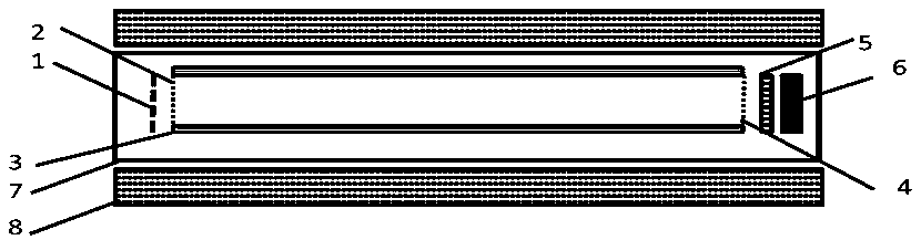
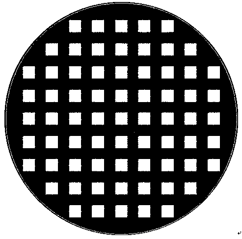
[0033] Such as figure 2 As shown, the holes of the dot matrix cathode in this embodiment are square. The non-magnetic metal mesh of the lattice cathode 1 is a copper mesh with a thickness of 100 μm. The copper mesh has no photoelectric effect and is opaque, and the material of the transmissive photocathode is gold. The outer diameter of the lattice cathode 1 is Φ10mm, the period of the copper mesh is 100μm, each hole is a square with a side length of 50μm, and the substrate of the transmissive photocathode is polyimide with a thickness of 100nm.

[0034] The shielding case of the magnetic coil 8 with shielding case is made of DT4C electromagnetic pure iron material, and the thickness of the shielding case is 5mm. The ampere-turns of the magnetic coil with a shielded shell, that is, the current value × the number of turns, is 400000A × N, the inner diameter of the coil is Φ30mm, and the outer diameter is Φ66mm. The magnetic field intensity generated by the shielded magnetic ...

Embodiment 2

[0037] The implementation of this embodiment is basically the same as that of Embodiment 1, the main differences are as image 3 As shown, the holes of the lattice cathode in this embodiment are circular with a diameter of 50 μm, the material of the transmissive photocathode is cesium iodide, and the period of the non-magnetic metal mesh is 90 μm.


PUM

PropertyMeasurementUnit
The inside diameter ofaaaaaaaaaa
Caliberaaaaaaaaaa
Amplitudeaaaaaaaaaa

Abstract

The invention discloses a lattice-structured electron drift tube. The lattice cathode of the electron drift tube converts X-rays radiated by a target into electron pulse strings distributed in a spatial array, the electron pulse strings drift at a high speed under the action of a gradual change electric field with non-interfering spatial arrays, and the spatial scale of the electron pulse stringsin the drift is fully guaranteed. The electron pulse strings pass through a rear-end grid mesh distributed in an equal-ratio space array, is multiplied by a microchannel plate and then bombards a fluorescent screen to emit light, and the electric signal is converted into an optical signal again, and the electron pulse strings are in a uniform magnetic field generated by a magnetic coil with a shielding shell in the whole process. The electron drift tube can obviously improve the spatial resolution characteristic in an electron uniform-speed drift region, furthest reduce the spatial transversecrosstalk of the electron pulse strings by utilizing the magnetic field constraint, achieve spatial fidelity and a large dynamic range, contribute to promoting the development of an ultrahigh time-resolution two-dimensional imaging diagnosis technology, and have important significance for improving the precision level of laser inertial constraint fusion diagnosis.

Description

technical field [0001] The invention belongs to the field of X-ray ultrafast imaging, and in particular relates to a lattice configuration electron drift tube. Background technique [0002] High-speed photography technology has a wide range of applications in the fields of medicine, biomedicine, laser fusion and aerospace. Most professional workers believe that optical recording technology with a time resolution of more than 1000 images per second and a spatial resolution of one to three spatial axes below a millimeter can be called high-speed photography. In fact, in the field of scientific research under extreme conditions, the temporal and spatial resolution requirements for ultrafast imaging devices are much higher than this. [0003] The plasma generated by laser targeting provides ideas for the study of matter interaction under extreme conditions, astrophysics, ultrafast phenomena and new controllable energy sources. The research of laser inertial confinement fusion ...

Claims


Application Information

Patent Timeline
IPC IPC(8): H01J29/02H01J29/54H01J29/66G21B1/23G21K4/00
CPCG21B1/23G21K4/00H01J29/023H01J29/54H01J29/66Y02E30/10
Inventor 曹柱荣袁铮王强强王峰杨家敏黎航陈韬邓博邓克立黎宇坤江少恩丁永坤
Owner LASER FUSION RES CENT CHINA ACAD OF ENG PHYSICS
Why Eureka
Try Eureka