
High-mechanical-strength quick self-positioning locking structure for optical fiber coupling

A mechanical strength, optical fiber coupling technology, applied in the optical field, can solve the problems of poor mechanical tolerance, optical signal insertion loss, high mode transmission, poor positioning, etc.

Pending Publication Date: 2019-09-03
长春光吉科技有限责任公司
View PDF0 Cites 0 Cited by
  • Summary
  • Abstract
  • Description
  • Claims
  • Application Information

AI Technical Summary

Problems solved by technology

[0002] At present, the optical fiber coupling structure is aimed at two different purposes: one is a coupling method for high-energy laser transmission. There are high requirements for conduction efficiency and mechanical tensile resistance. This structure on the market is a screw-locking structure represented by the SMA905 standard. The disadvantage of this structure is poor positioning, and professional equipment is required for each fiber insertion and removal. The coupling adjustment of the optical fiber is to ensure the transmission rate of the optical power, which is difficult to satisfy the fiber transmission system that requires frequent plugging and unplugging; the other is the coupling method for low-energy laser transmission, which is used for optical fiber communication , it has higher requirements on the dispersion, insertion loss and mode transmission of optical signals. This kind of structure in the market is based on SC or LC as the standard insertion locking structure. Because optical fiber communication uses poor tensile strength Single-mode fiber, so this coupling structure does not take mechanical tolerance into account, and its disadvantage is poor mechanical tolerance
[0003] None of the existing technologies can meet the requirements of high mechanical tolerance. The positioning of the SMA905 fiber coupling structure is poor, the coupling is difficult and slow, and the light transmission efficiency of the SC / LC fiber coupling structure is low, and the anti-damage threshold is low. Therefore, it is urgent to develop a High mechanical strength fast self-positioning locking structure for fiber coupling

Method used


Image

  • High-mechanical-strength quick self-positioning locking structure for optical fiber coupling

Examples


Embodiment Construction

[0019] In order to make the above objects, features and advantages of the present invention more comprehensible, specific implementations of the present invention will be described in detail below in conjunction with the accompanying drawings.

[0020] In the following description, a lot of specific details are set forth in order to fully understand the present invention, but the present invention can also be implemented in other ways different from those described here, and those skilled in the art can do it without departing from the meaning of the present invention. Similarly generalized, the present invention is therefore not limited by the specific embodiments disclosed below.

[0021] Secondly, the present invention is described in detail in conjunction with schematic diagrams. When describing the implementation of the present invention in detail, for the convenience of explanation, the cross-sectional view showing the device structure will not be partially enlarged accor...


PUM


Abstract

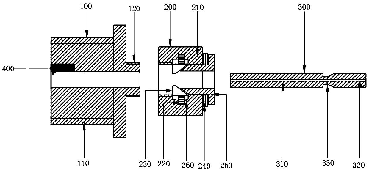
The invention belongs to the technical field of optics, and particularly relates to a high-mechanical-strength quick self-positioning locking structure for optical fiber coupling. The structure comprises a coupling constraint part, a coupling fixing part and an optical fiber fixing part, wherein the coupling constraint part comprises a coupling constraint main body and a connecting block, the connecting block is fixedly installed on the right side wall of the coupling constraint main body, the coupling fixing part is fixedly installed on the right side wall of the coupling constraint main bodyand comprises a coupling fixing main body, a first spring, a positioning fixing wedge, a second spring and a positioning fixing wedge groove, a plurality of positioning fixing wedge grooves are formed in the middle of the inside of the coupling fixing main body, and the inner walls of the plurality of positioning fixing wedge grooves are clamped with the first spring. According to the invention,an optical fiber fixing rod is locked at a required position accurately, stably and more robustly, an optical fiber and a laser system are rapidly combined and separated simultaneously, and the comprehensive effect of mechanical strength is improved.

Description

technical field [0001] The invention relates to the field of optical technology, in particular to a fast self-positioning locking structure with high mechanical strength for optical fiber coupling. Background technique [0002] At present, the optical fiber coupling structure is aimed at two different purposes: one is a coupling method for high-energy laser transmission. There are high requirements for conduction efficiency and mechanical tensile resistance. This structure on the market is a screw-locking structure represented by the SMA905 standard. The disadvantage of this structure is poor positioning, and professional equipment is required for each fiber insertion and removal. The coupling adjustment of the optical fiber is to ensure the transmission rate of the optical power, which is difficult to satisfy the fiber transmission system that requires frequent plugging and unplugging; the other is the coupling method for low-energy laser transmission, which is used for opt...

Claims


Application Information

Patent Timeline
IPC IPC(8): G02B6/38
CPCG02B6/3855G02B6/3847G02B6/3825
Inventor 王治洋黄旭张程承刘颂
Owner 长春光吉科技有限责任公司
Learn More