High-efficiency selective emitter solar cell diffusion process
A solar cell and diffusion process technology, applied in the field of solar cells, can solve the problems of low Uoc, low Isc, and poor square resistance uniformity of the battery, and achieve the effects of improving square resistance uniformity, good metallization contact, and solving compatibility problems.
- Summary
- Abstract
- Description
- Claims
- Application Information
AI Technical Summary
Problems solved by technology
Method used
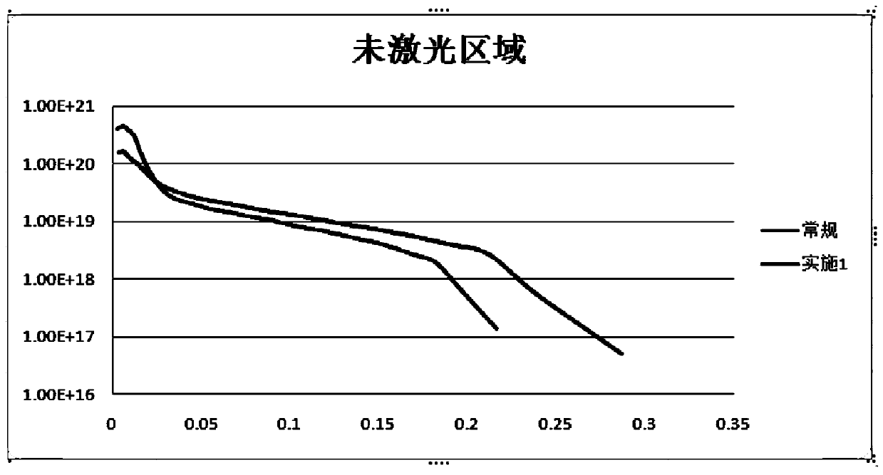
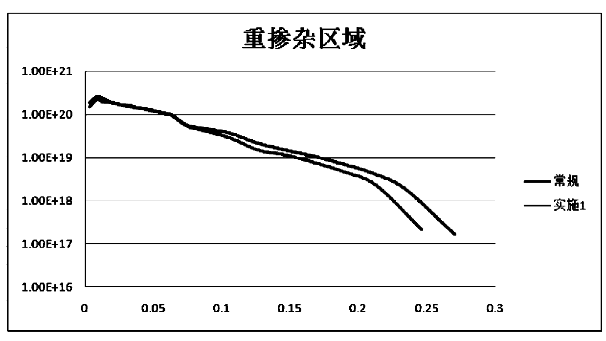
Image

Examples
Embodiment Construction
[0030] The present invention will now be described in further detail in conjunction with the accompanying drawings and preferred embodiments. These drawings are all simplified schematic diagrams, which only illustrate the basic structure of the present invention in a schematic manner, so they only show the configurations related to the present invention.
[0031] A high-efficiency selective emitter solar cell diffusion process, comprising the following steps:
[0032] 1. Entering the boat: time 500-600s, temperature 750-780℃, large nitrogen 2-5slm;
[0033] 2. Heating: time 200-300s, temperature 750-780°C, large nitrogen 1-2slm;
[0034] 3. Constant temperature: time 100-200s, temperature 750-780°C, large nitrogen 0.5-1slm;
[0035] 4. Oxidation: time 300-400s, temperature 790-800°C, large nitrogen 1-5slm, oxygen flow 1-2slm;
[0036] 5. Deposition 1: time 400-600s, temperature 790-800°C, large nitrogen 1-5slm, oxygen flow 0.5-1.5slm, small nitrogen flow 0.5-1.2slm;
[003...
PUM
 Abstract
Description
Claims
Application Information
 - R&D
- Intellectual Property
- Life Sciences
- Materials
- Tech Scout
- Unparalleled Data Quality
- Higher Quality Content
- 60% Fewer Hallucinations
Browse by: Latest US Patents, China's latest patents, Technical Efficacy Thesaurus, Application Domain, Technology Topic, Popular Technical Reports.
© 2025 PatSnap. All rights reserved.Legal|Privacy policy|Modern Slavery Act Transparency Statement|Sitemap|About US| Contact US: help@patsnap.com