MMC direct current power transmission line fault recognition method based on correlation
A DC transmission line and fault identification technology, applied in the direction of measuring electricity, measuring electrical variables, measuring devices, etc., can solve problems such as harsh conditions, long line distances, complex working environments, etc., and achieve the effect of sensitive identification
- Summary
- Abstract
- Description
- Claims
- Application Information
AI Technical Summary
Problems solved by technology
Method used
Image
Examples
Embodiment 1
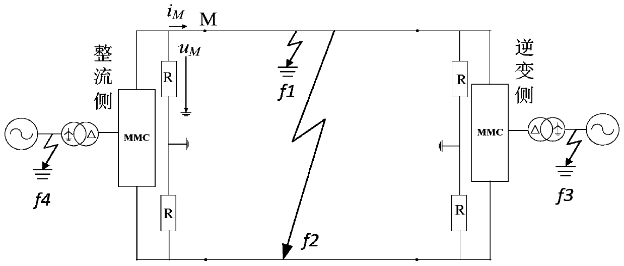
[0026] Example 1: Establish as attached figure 1 The MMC HVDC transmission system shown is used as a simulation model. The winding on the valve side of the connecting transformer adopts a delta connection without a neutral point, and the AC side of the connecting transformer adopts a star connection, and its neutral point is directly grounded. The DC side is grounded through the clamping resistor, which has a large resistance value. Its main function is to clamp the two-pole voltage and provide a potential reference point for the DC system during normal operation. The DC voltage is ±320kV, the transmission line is 400km, and M is the measurement terminal.
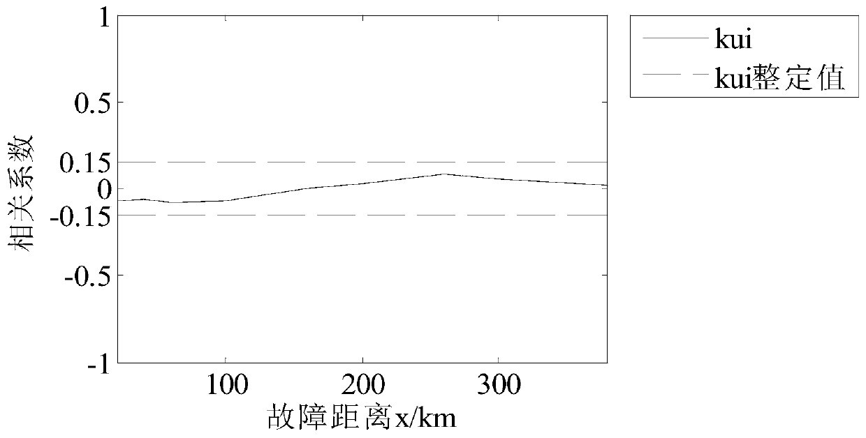
[0027] (1) Fault location: positive ground fault f 1 , 200km away from the measuring end; the fault start time is 0.4s; the sampling frequency is 10kHz.
[0028] (2) Acquire fault voltage and current data at the measurement point according to the first step in the manual.
[0029] (3) According to the second step in the...
Embodiment 2
[0032] Example 2: Establish as attached figure 1 The MMC HVDC transmission system shown is used as a simulation model. The winding on the valve side of the connecting transformer adopts a delta connection without a neutral point, and the AC side of the connecting transformer adopts a star connection, and its neutral point is directly grounded. The DC side is grounded through the clamping resistor, which has a large resistance value. Its main function is to clamp the two-pole voltage and provide a potential reference point for the DC system during normal operation. The DC voltage is ±320kV, the transmission line is 400km, and M is the measurement terminal.
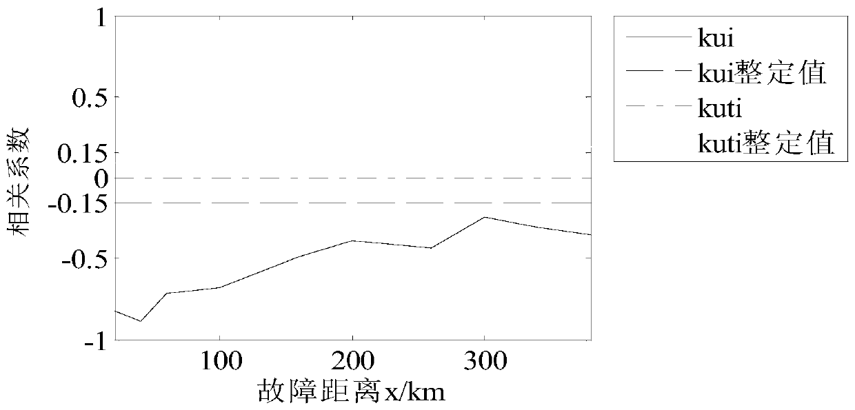
[0033] (1) Fault location: bipolar short circuit fault f 2 , 200km away from the measuring end; the fault start time is 0.4s; the sampling frequency is 10kHz.
[0034] (2) Acquire fault voltage and current data at the measurement point according to the first step in the manual.
[0035] (3) Take the fault voltage and cu...
Embodiment 3
[0038] Example 3: Establish as attached figure 1 The MMC HVDC transmission system shown is used as a simulation model. The winding on the valve side of the connecting transformer adopts a delta connection without a neutral point, and the AC side of the connecting transformer adopts a star connection, and its neutral point is directly grounded. The DC side is grounded through the clamping resistor, which has a large resistance value. Its main function is to clamp the two-pole voltage and provide a potential reference point for the DC system during normal operation. The DC voltage is ±320kV, the transmission line is 400km, and M is the measurement terminal.
[0039] (1) Fault location: three-phase short-circuit ground fault on the AC side of the inverter station f 3 ; The start time of the fault is 0.4s; the sampling frequency is 10kHz.
[0040] (2) Acquire fault voltage and current data at the measurement point according to the first step in the manual.
[0041] (3) Take th...
PUM
 Abstract
Description
Claims
Application Information
 - R&D
- Intellectual Property
- Life Sciences
- Materials
- Tech Scout
- Unparalleled Data Quality
- Higher Quality Content
- 60% Fewer Hallucinations
Browse by: Latest US Patents, China's latest patents, Technical Efficacy Thesaurus, Application Domain, Technology Topic, Popular Technical Reports.
© 2025 PatSnap. All rights reserved.Legal|Privacy policy|Modern Slavery Act Transparency Statement|Sitemap|About US| Contact US: help@patsnap.com


