
A control method of waste heat recovery system

A waste heat recovery system and control method technology, applied in the direction of indirect heat exchangers, heat exchanger types, heat exchange equipment, etc., can solve the problems that the recovered heat is not stable enough, uncontrollable, and unable to perform stable output, etc., to prevent Effects of heat exchange, improved recovery, and increased stability

Active Publication Date: 2020-11-10
HUADING POWER SUPPLY TIANJIN CO LTD
View PDF8 Cites 0 Cited by
  • Summary
  • Abstract
  • Description
  • Claims
  • Application Information

AI Technical Summary

Problems solved by technology

[0002] The gas cogeneration system is a new type of energy system, which mainly uses combustible gas to generate electricity and recovers the waste heat after combustion. It has the advantages of high comprehensive efficiency, energy saving and environmental protection; but the recovered heat is not stable enough and cannot be controlled. , unable to perform stable output, which is not conducive to the reuse of recovered heat

Method used


Image

  • A control method of waste heat recovery system
  • A control method of waste heat recovery system
  • A control method of waste heat recovery system

Examples


Embodiment Construction

[0034] In order to enable those skilled in the art to better understand the technical solution of the present invention, the present invention will be described in detail below in conjunction with the accompanying drawings. The description in this part is only exemplary and explanatory, and should not have any limiting effect on the protection scope of the present invention. .

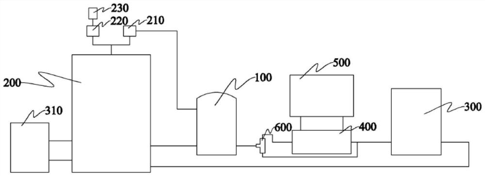
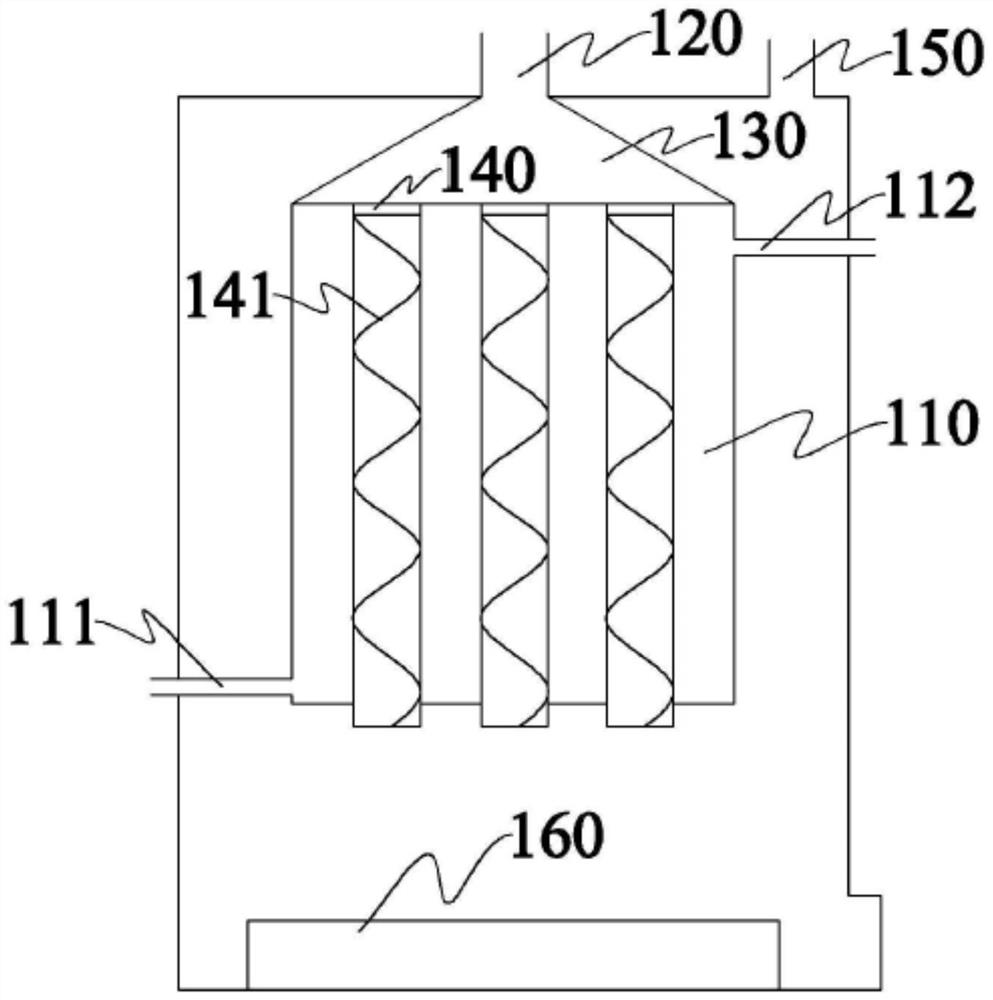
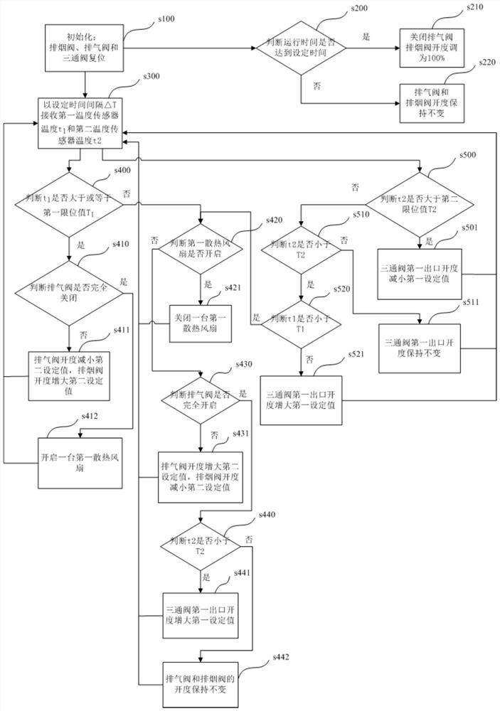
[0035] Please refer to figure 1 , the present embodiment provides a waste heat recovery system, including a generator set 200 and a PLC module; the inside of the generator set 200 is provided with a high-temperature cooling pipeline, and the high-temperature cooling pipeline is connected to an external high-temperature water circulation device; the outlet of the high-temperature cooling pipeline A first temperature sensor is provided; a parallel exhaust valve 210 and a smoke exhaust valve 220 are provided at the exhaust port of the generator set 200, and the exhaust valve 210 is connected to the waste ...


PUM


Abstract

The invention provides a waste heat recovery system and a control method thereof. The waste heat recovery system comprises a power generator set, a PLC module and a high-temperature water cycling device connected with the power generator set; an air exhaust port of the power generator set is provided with an air exhaust valve and a fume exhaust valve; the air exhaust valve is connected with the waste heat boiler; the high-temperature water cycling device comprises a high-temperature water tank; a plurality of first cooling fans are arranged on the high-temperature water tank; the waste heat boiler is connected to a position between an inlet of the high-temperature water tank and the power generator set; a heat exchanger is connected to a position between the waste heat boiler and the high-temperature water tank; a shunting three-way valve is connected to a position between the waste heat boiler and the heat exchanger; and a first outlet of the three-way valve is connected with an inletof a heat medium pipeline of the heat exchanger, and a second outlet of the three-way valve is connected with the high-temperature water tank. According the technical scheme provided by the embodiment of the invention, the heat source quantity of heat exchange can be controlled through the three-way valve so as to control heat output; the water temperature of high-temperature water circulation loop can be controlled through the air exhaust valve and the first cooling fans, so that the power generator set is cooled and the stable output is controlled.

Description

technical field [0001] This application relates to the technical field of cogeneration of heat and power, and in particular to a waste heat recovery system and a control method thereof. Background technique [0002] The gas cogeneration system is a new type of energy system, which mainly uses combustible gas to generate electricity and recovers the waste heat after combustion. It has the advantages of high overall efficiency, energy saving and environmental protection; but the recovered heat is not stable enough and cannot be controlled. , unable to perform stable output, which is not conducive to the reuse of recovered heat. Contents of the invention [0003] In view of the above defects or deficiencies in the prior art, it is desired to provide a waste heat recovery system and a control method thereof. [0004] In the first aspect, the present application provides a waste heat recovery system, including a generator set, a PLC module, and a high-temperature water circula...

Claims


Application Information

Patent Timeline
Patent Type & Authority Patents(China)
IPC IPC(8): F28D7/16F28F27/02F02G5/02
CPCF02G5/02F28D7/16F28F27/02Y02T10/12
Inventor 张辉
Owner HUADING POWER SUPPLY TIANJIN CO LTD
Learn More