
Pull-type drilling rig derrick base structure

A trailer-type and derrick technology, which is applied to drilling equipment, earthwork drilling, drilling equipment and methods, etc., can solve the problems of limited use area, many transportation trips, and high transportation costs

Pending Publication Date: 2019-08-30
SICHUAN HONGHUA PETROLEUM EQUIP
View PDF0 Cites 5 Cited by
  • Summary
  • Abstract
  • Description
  • Claims
  • Application Information

AI Technical Summary

Problems solved by technology

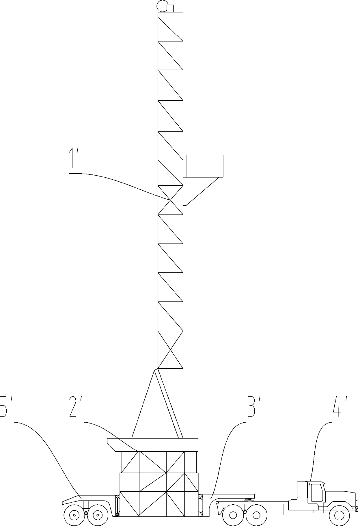
[0006] 1. In the prior art, the drilling rig adopts a K-type derrick supporting a rotary base structure, which makes the installation and disassembly cumbersome and time-consuming, with many transportation trips and high transportation costs;
[0007] 2. In the prior art, the dragging and transportation of the derrick and the base are mostly carried out separately, and the derrick base needs to be assembled again after arriving at the well site, which takes a long time;
[0008] 3. The transportation height of the trailer drilling rig usually used in the prior art is greater than 40 meters, the transportation area is restricted and there are great safety hazards if the transportation height is too high;
[0009] 4. The derrick and base of the vehicle-mounted drilling rig usually used in the prior art need to be transported separately, and the derrick is a derrick with guy ropes, and the use area is limited. This increases the installation time and workload, especially not suitable for the working conditions where the drilling rig needs to be moved frequently in the cluster well operation;
[0010] 5. The quick-transfer drilling rig usually adopted in the prior art has detachable rear trailers and trailer frames respectively installed at the rear end and front end of the base, but the number of tires used in this structure is large (high cost), and often It is very difficult to reverse the alignment at the center of the wellhead, and the turning radius is large

Method used


Image

  • Pull-type drilling rig derrick base structure
  • Pull-type drilling rig derrick base structure
  • Pull-type drilling rig derrick base structure

Examples


Embodiment 1

[0115] Such as Figure 8 As shown, the base structure of the trailer-type drilling rig derrick includes a base assembly 2 connected to the foundation, a derrick assembly 1 movably connected with the base assembly 2, and a trailer frame assembly movably connected with the base assembly 2 and the derrick assembly 1 respectively. 3, also includes connecting fasteners 4 that are movably connected with the base assembly 2, the derrick assembly 1 and the trailer frame assembly 3, and the jacking cylinder that is fixedly connected with the trailer frame assembly 3 or the base assembly 2 5. The strut 6 that is movably connected with the connecting fastener 4, and the top of the trailer frame assembly 3 are fixedly equipped with a winch A, a hydraulic station B, a rope reversing machine C and a BOP control device.

[0116] In this embodiment, the number of jacking cylinders 5 is six, of which four jacking cylinders 5 are evenly and symmetrically distributed on both sides of the trailer...

Embodiment 2

[0123] Such as Figure 9 As shown, the base structure of the trailer-type drilling rig derrick includes a base assembly 2 connected to the foundation, a derrick assembly 1 movably connected with the base assembly 2, and a trailer frame assembly movably connected with the base assembly 2 and the derrick assembly 1 respectively. 3, also includes connecting fasteners 4 that are movably connected with the base assembly 2, the derrick assembly 1 and the trailer frame assembly 3, and the jacking cylinder that is fixedly connected with the trailer frame assembly 3 or the base assembly 2 5. The strut 6 that is movably connected with the connecting fastener 4, the tractor 7 that is movably connected with the front end of the trailer frame assembly 3, the trailer frame assembly 3, and the top is fixedly equipped with a winch A, a hydraulic station B, a rope reversing machine C and BOP control device.

[0124] In this embodiment, the number of jacking cylinders 5 is six, of which four j...

Embodiment 3

[0131] Such as Figure 10 As shown, the base structure of the trailer-type drilling rig derrick includes a base assembly 2 connected to the foundation, a derrick assembly 1 movably connected with the base assembly 2, and a trailer frame assembly movably connected with the base assembly 2 and the derrick assembly 1 respectively. 3, also includes connecting fasteners 4 that are movably connected with the base assembly 2, the derrick assembly 1 and the trailer frame assembly 3, and the jacking cylinder that is fixedly connected with the trailer frame assembly 3 or the base assembly 2 5. The strut 6 that is movably connected with the connecting fastener 4, the traction rod 9 that is movably connected with the front end of the trailer frame assembly 3, the tractor 7 that is movably connected with the traction rod 9, and the front end that is movably connected with the tail end of the derrick base 2. Field towing 8, the top of the trailer frame 3 is fixedly equipped with a winch A, ...


PUM


Abstract

The invention relates to the field of petroleum drilling and production equipment, in particular to an automated and modular pull-type drilling rig derrick base structure. The pull-type drilling rig derrick base structure comprises a base assembly connected with a foundation, a derrick assembly movably connected with the base assembly, and a trailer frame assembly movably connected with the base assembly and the derrick assembly, and further comprises connection fasteners movably connected with the base assembly, the derrick assembly and the trailer frame assembly correspondingly, jacking hydraulic cylinders fixedly connected with the trailer frame assembly or the base assembly, and supporting rods fixedly connected with the connection fasteners or the base assembly. The pull-type drillingrig derrick base structure has the beneficial effects that the turning radius is small, a using area is not limited, transferring can be conducted at a time, the mounting and carrying time is reduced, and automation and modularization are achieved.

Description

technical field [0001] The invention relates to the field of oil drilling and production equipment, in particular to an automatic and modularized trailer-type drilling rig derrick base structure. Background technique [0002] With the continuous development of drilling rig technology, the replacement speed of drilling rigs is accelerating, and the entire drilling rig is developing towards serialization, standardization, diversification and modularization. At the same time, the performance of drilling rigs has also been greatly improved. With the continuous advancement of technology, enterprises have higher and higher requirements for the automation of on-site operations, the time and cost spent in the process of moving drilling equipment. [0003] In recent years, in order to maximize benefits and reduce costs, various drilling contractors in the Middle East have clearly stipulated the moving time and number of moving trips of drilling rig equipment. The best choice for dri...

Claims


Application Information

Patent Timeline
Patent Type & Authority Applications(China)
IPC IPC(8): E21B7/02E21B15/00
CPCE21B7/02E21B15/00
Inventor 林靖杨淑娟杨欢冯强王刚邬柯梁帅曹晓东尹华卢国良李良久
Owner SICHUAN HONGHUA PETROLEUM EQUIP
Learn More