Excitation method and related device for an excitation system

A technology of an excitation system and a monitoring system, which is applied in the field of electric power, can solve problems such as excitation failure of the excitation system, misidentification, and influence on the operation stability of the excitation system. Effect

Active Publication Date: 2021-01-26
WUQIANG XISHUI POWER PLANT OF WULING ELECTRIC POWER CO LTD
View PDF6 Cites 0 Cited by
  • Summary
  • Abstract
  • Description
  • Claims
  • Application Information

AI Technical Summary

Problems solved by technology

At present, for the UNITROL5000 excitation system, it uses the generator terminal voltage and the excitation synchronous voltage as the excitation condition, and if there is an instantaneous voltage disturbance in any of the measurement circuits during excitation, the measurement circuit will be measured due to the voltage disturbance. If the voltage value exceeds the excitation cut-off voltage, the excitation system will mistakenly believe that the excitation is successful, and then enter the logic program of normal soft excitation, but during this period, the sampling values ​​of the generator terminal voltage and excitation current are all zero, After a certain period of time (usually 12 seconds), the soft excitation ends, and the excitation system will falsely report the action of over-excitation limit and rotor inverse time-limit over-current limitation, which will cause the excitation system to fail to activate, but no excitation failure signal will be reported, which will seriously affect the The operation stability of the excitation system and the success rate of unit startup

Method used


Image

  • Excitation method and related device for an excitation system
  • Excitation method and related device for an excitation system
  • Excitation method and related device for an excitation system

Examples


Embodiment approach

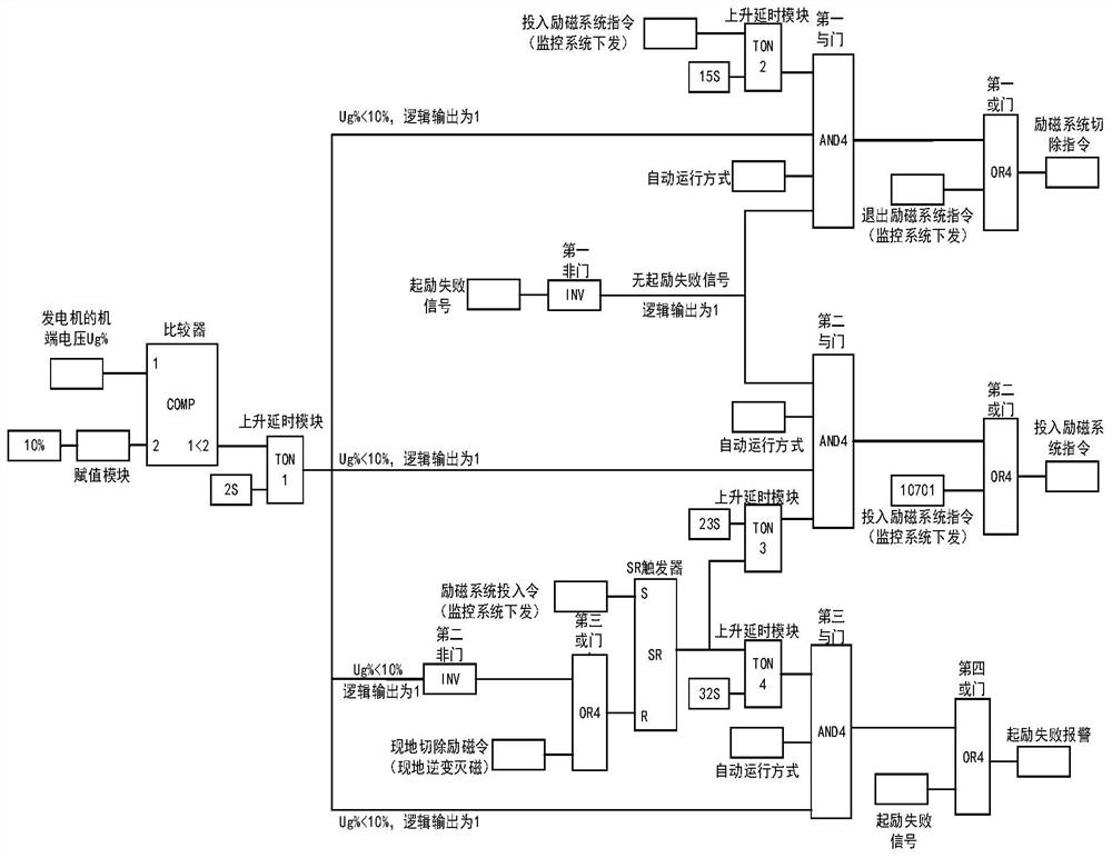
[0065]Monitor the terminal voltage of the generator and compare this terminal voltage with 10% of the rated terminal voltage. If the generator terminal voltage is less than 10% of the rated terminal voltage for 2 seconds, the delay module TON1 will rise Logic 1 is output 2 seconds after the comparator outputs logic 1. In addition, the monitoring system issues an excitation system input instruction, and the excitation system input instruction is maintained for 25 seconds. The rising delay module TON2 outputs logic 1 to the first AND gate after 15 seconds, while the rising delay module TON1 outputs logic 1 to the first AND gate after 15 seconds. An AND gate, if there is no excitation failure signal, the first NOT gate outputs logic 1 to the first AND gate, and if the control mode of the excitation system is automatic control, the first AND gate outputs logic 1, thus the first OR The gate outputs logic 1, which means that the conditions of the de-excitation system are met, and then the...


PUM


Abstract

The invention discloses an excitation method of an excitation system; the excitation method comprises the following steps of monitoring the generator terminal voltage of a generator and judging whether the generator terminal voltage is smaller than the rated generator terminal voltage of a preset ratio or not; if so, judging whether the excitation system meets a de-excitation system condition or not after the first preset duration when the monitoring system issues an excitation system input command; if the de-excitation system condition is met, sending an excitation system cutting-off instruction to enable the excitation system to exit; judging whether the excitation system meets an input excitation system condition or not after the second preset duration when the monitoring system issuesan excitation system input command, wherein the second preset duration is longer than the first preset duration; and if the input excitation system condition is met, inputting the excitation system for performing excitation of the excitation system. According to the method, the running stability of the excitation system can be effectively improved, and the starting success rate of the unit can beimproved. The invention further discloses an excitation device of the excitation system, the excitation system and a computer readable storage medium which all have the technical effects.

Description

Technical field[0001]This application relates to the field of electric power technology, and in particular to an excitation system excitation method; also relates to an excitation system excitation device, an excitation system and a computer-readable storage medium.Background technique[0002]With the development of power construction, the power system has entered the stage of large networks, high voltages, and large units. The stability of the operation of large-capacity units is essential to the stability and safety of the overall grid. Among them, the excitation system of the generator set has the greatest impact on generator stability. The excitation system is not only a guarantee for stable operation of the unit, but also a lever for reactive power and voltage regulation in the entire grid. At present, for the UNITROL5000 excitation system, it uses the measurement of the generator terminal voltage and the excitation synchronization voltage as the excitation condition, and if any ...

Claims


Application Information

Patent Timeline
Patent Type & Authority Patents(China)
IPC IPC(8): H02P9/08
CPCH02P9/08
Inventor 鲁秉宸杨敬飚刘献忠
Owner WUQIANG XISHUI POWER PLANT OF WULING ELECTRIC POWER CO LTD
Why Eureka
Try Eureka