Method for operating a spinning device of a rotor spinning machine and spinning device of a rotor spinning machine

A technology of rotor spinning machine and rotor cup, which is applied in one aspect of the spinning device, can solve the problems of inhaling impurities, and achieve the effect of avoiding non-productive downtime

Active Publication Date: 2022-06-21
MASCHINENFABRIK RIETER AG
View PDF14 Cites 0 Cited by
  • Summary
  • Abstract
  • Description
  • Claims
  • Application Information

AI Technical Summary

Problems solved by technology

However, if the filter becomes fouled, it will still pick up impurities and the filter must be cleaned

Method used


Image

  • Method for operating a spinning device of a rotor spinning machine and spinning device of a rotor spinning machine
  • Method for operating a spinning device of a rotor spinning machine and spinning device of a rotor spinning machine
  • Method for operating a spinning device of a rotor spinning machine and spinning device of a rotor spinning machine

Examples


Embodiment Construction

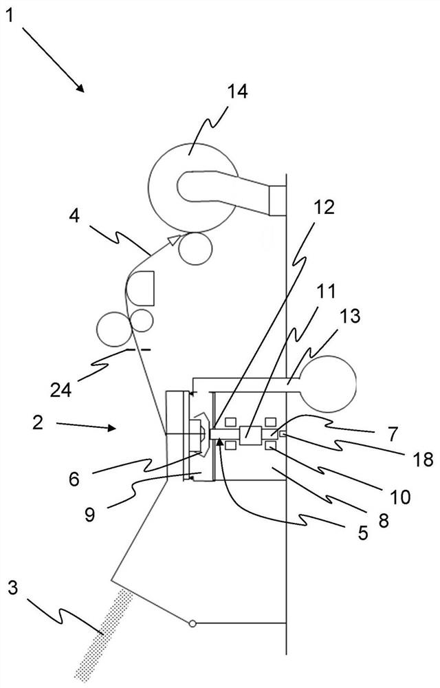
[0073] figure 1 A schematic side view of a rotor spinning machine 1 with a spinning device 2 is shown. By means of the spinning device 2 , the yarn 4 can be spun from the fiber material 3 , which can be wound on a reel 14 . The spinning device 2 has a spinning rotor 5 by means of which yarns 4 are formed from the fiber material 3 during operation of the rotor spinning machine 1 .

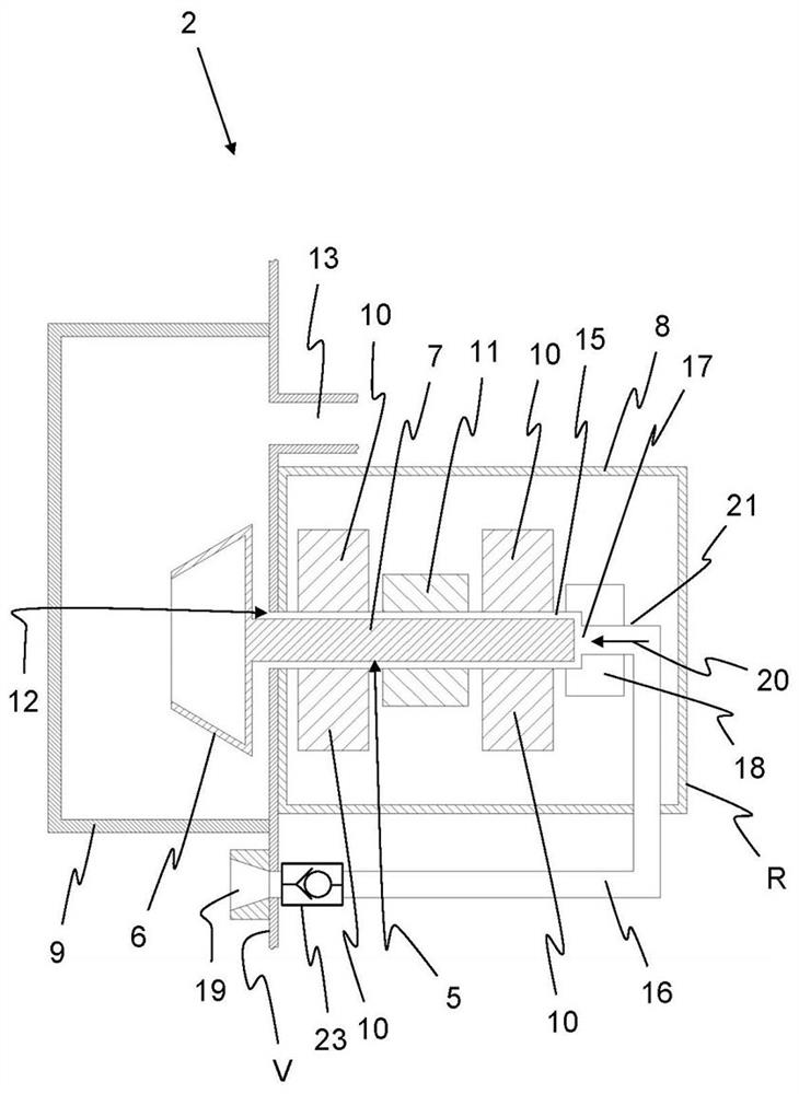
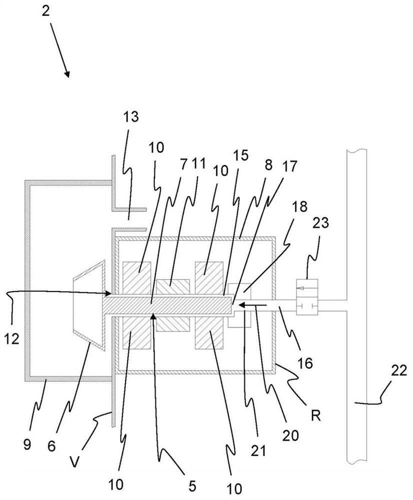
[0074] The spinning rotor 5 has a rotor cup 6 and a rotor shaft 7 . In order to form the yarn 4 from the fiber material 3 , the fiber material is guided into the rotor cup 6 during the rotation of the spinning rotor 5 . By means of the rotation of the spinning rotor 5, the yarn 4 is formed. The spinning rotor 5 can be driven by a drive 11 , which is designed in particular as an electrodynamic single drive. The rotational speed of the spinning rotor 5 can be counted here as 150,000 1 / min or more, which places high demands on the bearing 10 of the spinning rotor 5 . The bearing 10 and the drive 1...


PUM


Abstract

In the method of operating the spinning device (2) of a rotor spinning machine (1), the spinning rotor (5) with the rotor cup (6) and the rotor shaft (7) is and the drive (11) operatively connected to the rotor shaft rotates and the rotor shaft is supported in the drive housing by means of bearings (10, 18), the rotor cup is in the rotor housing (9) loaded with negative pressure and the rotor shaft Extending through the connection opening (12) between the drive housing and the rotor housing, so that the drive housing is also under negative pressure during spinning, compressed air is supplied to the drive housing via the air inlet. Compressed air is supplied to the drive housing via the air intake, and the drive housing and / or the bearings are cleaned at intervals, preferably at adjustable intervals. The corresponding spinning device of the rotor spinning machine has a control unit for controlling the compressed air supply, by means of which compressed air can be supplied to the drive housing via the air supply at intervals, preferably at adjustable time intervals.

Description

technical field [0001] The invention relates to a method for operating a spinning device of a rotor spinning machine, in which a spinning rotor with a rotor cup and a rotor shaft is rotated by means of a drive arranged in a drive housing, wherein the drive is in operative connection with the rotor shaft and is mounted in the drive housing by means of non-contact bearings, in particular magnetic bearings, wherein the rotor cup is arranged in the rotor housing, which is negatively pressure. Furthermore, the rotor shaft extends through the connecting opening between the drive housing and the rotor housing, so that the drive housing is also under negative pressure during the spinning process. Compressed air is fed into the drive housing through the intake end. Furthermore, the present invention relates to a spinning device of a rotor spinning machine. Background technique [0002] In such spinning devices, it is not possible to completely seal between the drive housing and th...

Claims


Application Information

Patent Timeline
Patent Type & Authority Patents(China)
IPC IPC(8): D01H4/10D01H4/12
CPCD01H4/10D01H4/12D01H4/24D01H11/005F16C32/0476
Inventor M·库布勒康斯坦汀·里格
Owner MASCHINENFABRIK RIETER AG
Why Eureka
Try Eureka