A Dynamic Extrapolation Method for Bandwidth-Limited Signals

A bandwidth-limited, push method technology, applied in the field of signal processing, can solve problems such as low reliability and low efficiency, and achieve the effects of improving reliability, improving effectiveness, and reducing normalized mean square error

Active Publication Date: 2020-12-25
HARBIN INST OF TECH
View PDF4 Cites 0 Cited by
  • Summary
  • Abstract
  • Description
  • Claims
  • Application Information

AI Technical Summary

Problems solved by technology

[0004] The purpose of the present invention is to solve the problem of low efficiency of the traditional extrapolation method when the observation time is relatively small and the low reliability of the traditional extrapolation method when the iterative filter bandwidth is larger than the signal bandwidth, and proposes a dynamic extrapolation method for bandwidth-limited signals. push method

Method used


Image

  • A Dynamic Extrapolation Method for Bandwidth-Limited Signals
  • A Dynamic Extrapolation Method for Bandwidth-Limited Signals
  • A Dynamic Extrapolation Method for Bandwidth-Limited Signals

Examples


specific Embodiment approach 1

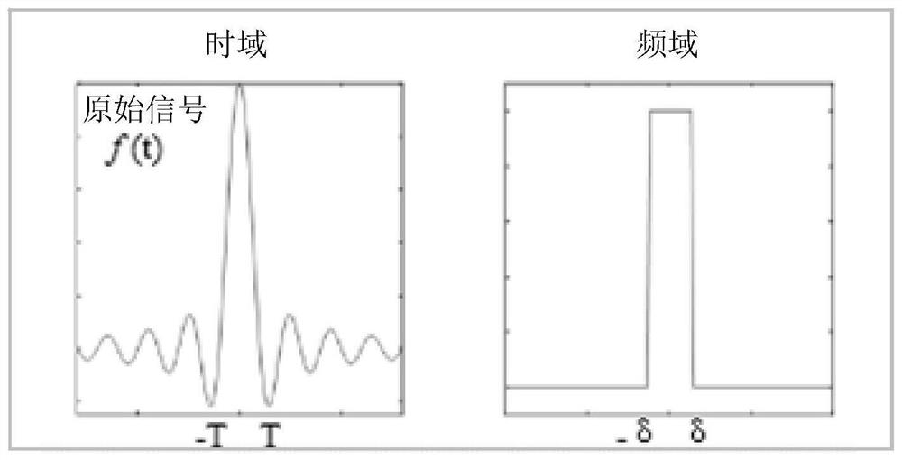
[0019] Specific embodiment one: a kind of OFDM transmission method of frequency offset described in this embodiment, take the sinc signal as an example (this signal is a frequency-domain band-limited signal), according to the dynamic extrapolation process of the time-domain observation signal, the method Include the following steps:

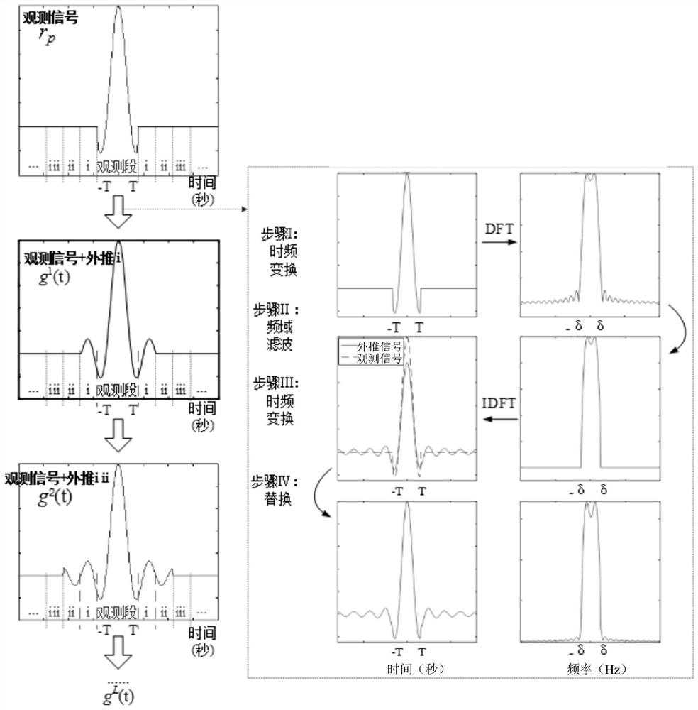
[0020] Step 1. According to the compression ratio α, the observed signal r p Pad zero to the length of the original signal, use the zero padding area as the area to be extrapolated, and averagely segment the area to be extrapolated, and number each segment of the signal as 1, 2 in order of distance from the observation position from near to far ,...,L;

[0021] Step 2. Initialize the signals of each segment respectively, and obtain the initialization extrapolation signal of the first segment signal and the support set ψ of the first segment signal p,l , l=1,2,...,L;

[0022] Step 3: Dynamic iterative extrapolation is performed on the initial e...

specific Embodiment approach 2

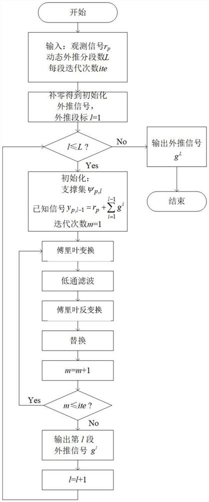
[0025] Specific implementation mode two: as figure 1 , figure 2 and image 3 As shown, the difference between this embodiment and the first embodiment is that the specific process of the third step is:

[0026] Step 31. Set the maximum number of iterations of dynamic iterative extrapolation to ite according to the amount of calculation or performance required by the system, and the initial extrapolation signal of the l-section signal to be y p,l-1 ;

[0027] Step 32. In the first iteration, for y p,l-1 Perform discrete Fourier transform to obtain the frequency domain signal Y p,l-1 ;

[0028] Step 33, the frequency domain signal Y p,l-1 Through iterative filter H d , to obtain the filtered signal

[0029] Step three and four, the filtered signal Perform an inverse discrete Fourier transform to obtain a mapped signal in the time domain

[0030] Step three and five, use the mapping signal not in the support set ψ p,l part of y p,l-1 Substitution is performed ...

specific Embodiment approach 3

[0038] Specific implementation mode three: the difference between this implementation mode and specific implementation mode two is: the specific process of described steps three and five is:

[0039]

[0040] Among them: k stands for discrete signal The kth point in , represent a discrete signal The value of the kth point in y p,l-1 (k) represents the signal y p,l-1 The value of the kth point in (k), representative signal The value of the kth point in .

[0041] Then for the second iteration:

[0042]

[0043] in: represents the mapped signal in the time domain obtained in the second iteration.


PUM


Abstract

The invention relates to a dynamic extrapolation method of a bandwidth-limited signal, which belongs to the technical field of signal processing. The invention solves the problems of low efficiency of the traditional extrapolation method when the observation time is relatively small and low reliability of the traditional extrapolation method when the iterative filter bandwidth is larger than the signal bandwidth. The present invention improves the extrapolation accuracy when the initial energy of the observation signal is relatively small by treating the extrapolation signal segmented and sequentially extrapolating, and solves the problem of the traditional Gerchberg-Papoulis extrapolation algorithm (referred to as GP algorithm) when the observation time is relatively small. Low-efficiency extrapolation problem, and the low-reliability extrapolation problem when the iterative filter bandwidth is greater than the signal bandwidth, when the computational complexity is fixed, under the requirements of a certain extrapolation performance index, the dynamic extrapolation method of the present invention can improve the GP algorithm The effectiveness of the GP algorithm improves the reliability of the GP algorithm in scenarios where the signal bandwidth is uncertain within a certain range. The invention can be applied to the technical field of signal processing.

Description

technical field [0001] The invention belongs to the technical field of signal processing, and in particular relates to a dynamic extrapolation method of a bandwidth-limited signal. Background technique [0002] In wireless communication, medical imaging, radar imaging, satellite positioning and other environments, the signal is often only able to detect part of the data, or part of the data that is less disturbed, due to the limitation of the channel environment or the detection instrument itself. If the observed partial data g(t) (g(t) is part of the original signal f(t) data) can be used to obtain the f(t) data on the entire area, the effectiveness of the system will be greatly improved ; If the transmission method can be designed according to the channel environment and based on the idea of ​​extrapolation, the reliability of the system will be improved. [0003] Most signals in the field of signal processing can be mapped to a certain domain through some transformation,...

Claims


Application Information

Patent Timeline
Patent Type & Authority Patents(China)
IPC IPC(8): G06K9/00
CPCG06F2218/02
Inventor 沙学军张宇思房宵杰王迦祺
Owner HARBIN INST OF TECH
Why Eureka
Try Eureka