Wavefront detection method based on spatial frequency domain reference

A wavefront detection and spatial spectrum technology, applied in the field of wavefront detection based on spatial frequency domain reference, can solve the problems of unguaranteed convergence, need to be improved, slow wavefront inversion, etc., and achieves easy integration and real-time performance. High and versatile effect

Active Publication Date: 2019-08-23
LASER FUSION RES CENT CHINA ACAD OF ENG PHYSICS
View PDF5 Cites 2 Cited by
  • Summary
  • Abstract
  • Description
  • Claims
  • Application Information

AI Technical Summary

Problems solved by technology

Interferometric wavefront measurement technology is characterized by extremely high detection accuracy, and is often used in surface shape detection of optical components and high-precision beam wavefront detection; Hartmann-Shack wavefront measurement technology divides the beam through a microlens array, Test the slope of each sub-beam to reconstruct the wavefront. Its structure is simple and solid, and it has been widely used in the fields of laser technology and astronomical detection. Curvature wavefront sensing technology can effectively detect low-order wavefront distribution, and is often used in The adaptive optics system of the electric deformable mirror improves the system control bandwidth; the mode wavefront sensing technology directly calculates the coefficients of each order aberration mode according to the distribution of light intensity, which can improve the wavefront detection speed; the phase difference wavefront measurement technology analysis The light intensity distribution at the focus and defocus positions is used to invert the wavefront, but due to the complexity of the algorithm, the real-time performance of the test needs to be improved; the pyramidal wavefront sensing technology uses the light beam at the focal plane of the prism to perform spectroscopic measurement for calculation and calculation, and the response speed is fast , the detection accuracy is high, and it has achieved important applications in the field of astronomical observation; the wavefront iterative reconstruction technology based on diffraction transmission is to restore the wavefront by testing the distribution of diffracted light intensity and using iterative algorithms such as G-S. Although the test system is simple, the wavefront The front inversion is slow and the convergence cannot be guaranteed

Method used


Image

  • Wavefront detection method based on spatial frequency domain reference
  • Wavefront detection method based on spatial frequency domain reference
  • Wavefront detection method based on spatial frequency domain reference

Examples


Embodiment 1

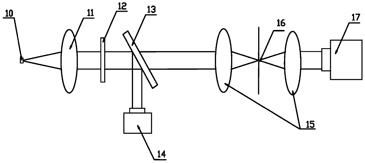
[0030] A wavefront detection method based on spatial frequency domain reference, using optical elements to perform two Fourier transforms on the light field of the beam to be measured, the optical elements including but not limited to lenses, parabolic mirrors and spherical mirrors. On the spatial spectrum plane after a Fourier transform, an asymmetric crosshair is introduced as a reference to modulate the light field. The modulation of the light field by the crosshair includes but is not limited to amplitude type and phase type. The light field after the second Fourier transform convolves the crosshair information, and the sensor is used to collect a single near-field intensity map after the second Fourier transform. Preferably, the sensor is a CMOS or CCD, and no introduction The dedicated wavefront sensor has a simple system and strong versatility. It divides a single near-field intensity map into several sub-regions. Under the condition that the number of sampling points in...

Embodiment 2

[0036] The same parts of this embodiment and the first embodiment will not be repeated, and the differences are:

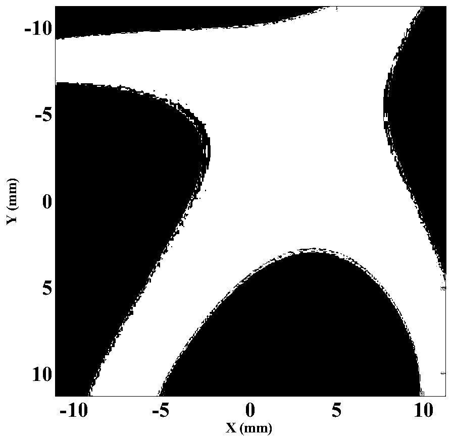
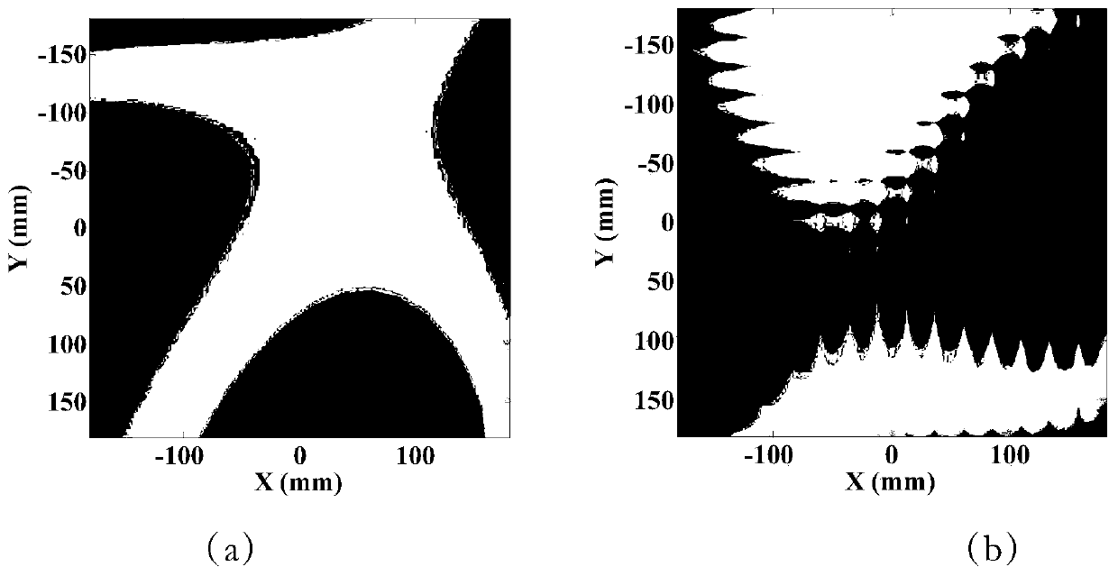
[0037] figure 2 is the wavefront distribution diagram of the beam to be measured, the PV value of the wavefront distortion of the beam to be measured is 4.79 μm, and the RMS value is 1.02 μm. image 3 (a) is the wavefront test result of the traditional Hartmann sensor, image 3 (b) is the wavefront test error diagram of the traditional Hartmann sensor. The PV value of the test error is 0.06 μm and the RMS value is 0.009 μm.

[0038] Using the wavefront detection method based on spatial frequency domain reference disclosed in the present invention, Figure 4 (a) is a single near-field intensity map collected by the CCD after the second Fourier transform, Figure 4 (b) is the near-field intensity distribution map of the first sub-region taken out, Figure 4 (c) is the sub-region Fourier transform map of the first sub-region, such as Figure 5 (a) and Figure ...


PUM


Abstract

The invention discloses a wavefront detection method based on spatial frequency domain reference, and relates to the technical field of wavefront detection. An optical element is used for carrying outtwo-time Fourier transformation on a light field of a light beam to be detected; an asymmetric crosshair is introduced in a spatial frequency spectrum surface after the first Fourier transformation to serve as a reference for modulation of the light field; a single near-field intensity map after the second Fourier transformation is collected; the single near-field intensity map is divided into aplurality of sub-regions; a wavefront slope of each sub-region is calculated; and wavefront distribution of the light beam to be detected is reconstructed through a region integral algorithm. Comparedwith a traditional wavefront measuring technology, a wavefront measuring result is irrelevant to an optical path aberration after the crosshair; no special calibration is needed; only the single near-field intensity map needs to be collected, and then the sub-region wavefront slope extraction and the wavefront reconstruction can be carried out; the real-time performance of wavefront measurement is relatively high; the implementation mode is simple; meanwhile, a special wavefront sensor does not need to be introduced; and the method is easy to integrate for use and high in universality.

Description

technical field [0001] The present invention relates to the technical field of wavefront detection, in particular to a wavefront detection method based on spatial frequency domain reference. Background technique [0002] The wavefront of the beam is an important parameter to describe the characteristics of the light field, and it is also an important information carrier. Obtaining the wavefront of the beam through the wavefront measurement technology can not only evaluate the physical properties of the light field, such as transmission ability, focusing ability, etc., but also obtain a lot of physical information, such as atmospheric turbulence distribution, optical element surface shape, optical system aberration, biological Tissue phase characteristics and flow field distribution characteristics, etc. At present, wavefront detection technology is widely used in adaptive optics, astronomical observation, optical component processing, laser system beam quality assessment, b...

Claims


Application Information

Patent Timeline
Patent Type & Authority Applications(China)
IPC IPC(8): G01J9/00
CPCG01J9/00G01J2009/002
Inventor 邓学伟王德恩袁强张鑫杨英赵军普陈良明胡东霞周维
Owner LASER FUSION RES CENT CHINA ACAD OF ENG PHYSICS
Why Eureka
Try Eureka